
Datasheet


Table Of Contents
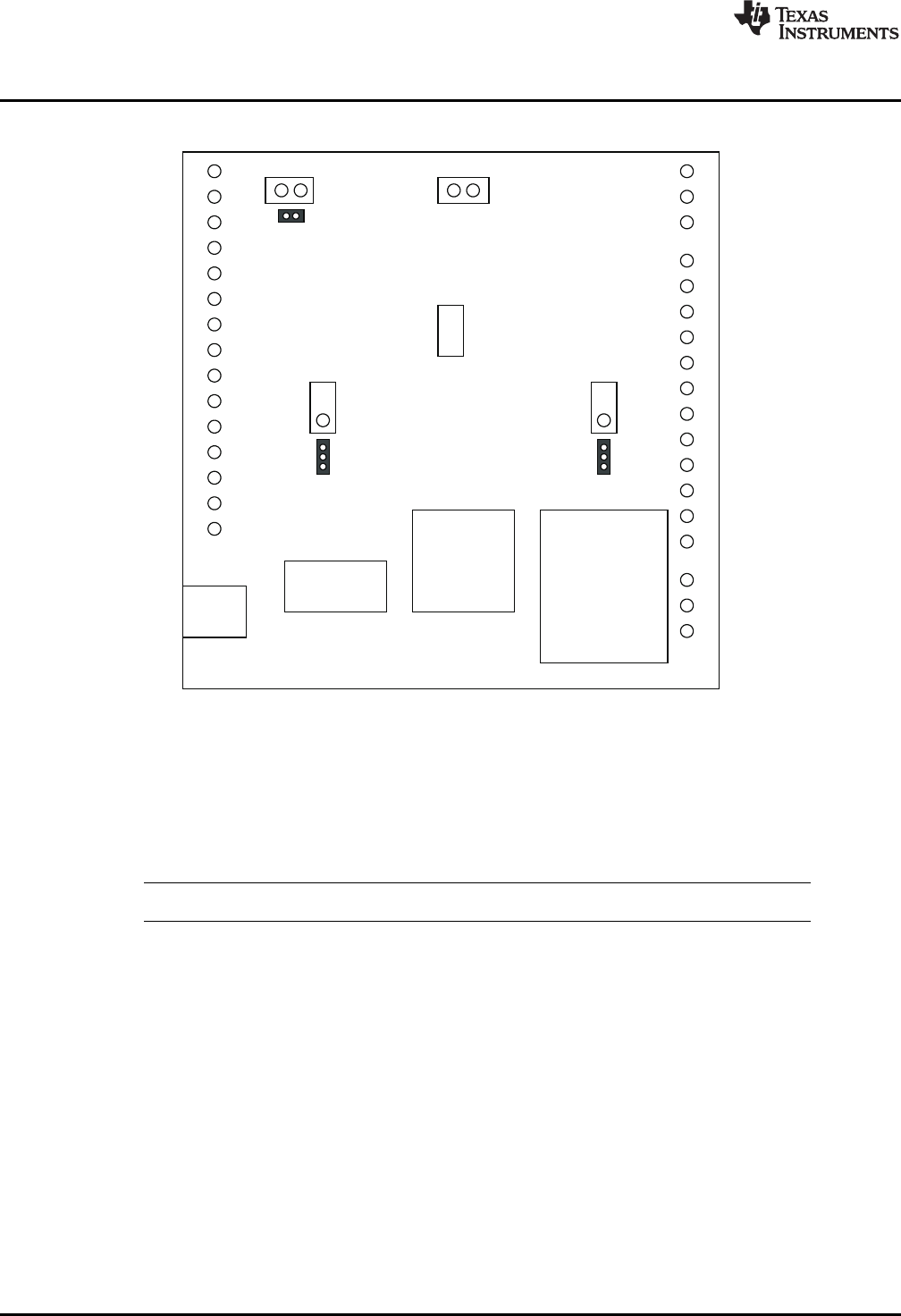
VM Power
DRV88xx
Motor Outputs
USB
Conn
USB Chip
MSP430
AVREF
DECAY
Proto Area
Where DRV88xx stands for one of DRV8840 or DRV8842
Block Diagram
www.ti.com
1 Block Diagram
1.1 Power Connectors
The CPG005_DRV88xx Customer EVM offers access to VM (Motor Voltage) power rail via a terminal
block (J1). A set of test clips in parallel with the terminal block allows for the monitoring of the input power
rail.
User must apply VM according to datasheet recommended parameters.
NOTE: VDD for logic and microcontroller is derived from USB interface.
1.2 Test Stakes
Every pin on the DRV88xx device has been brought out to a test stake. A label on the silkscreen identifies
each signal.
For those pins that change functionality depending on device flavor, a table is provided with corresponding
function name on its particular column.
1.3 Jumpers
There are only three jumpers the user must configure as detailed below. Default configuration assumes
microcontroller resources are being utilized. As an alternative, a variable resistance is provided on the
opposing jumper configuration.
2
CPG005_DRV88xx Evaluation Modules SLVU410–April 2011
Submit Documentation Feedback
Copyright © 2011, Texas Instruments Incorporated