DRV8833 Evaluation Module User's Guide Literature Number: SLVU498 July 2011
Copyright © 2011, Texas Instruments Incorporated SLVU498 – July 2011 Submit Documentation Feedback
Contents 1 2 3 4 Introduction ........................................................................................................................ Schematic .......................................................................................................................... PCB ................................................................................................................................... Connectors ................................................................................
Introduction 1 www.ti.com Introduction This document is provided with the DRV8833 customer evaluation module (EVM) as a supplement to the DRV8833 datasheet. It details the hardware implementation of the EVM.
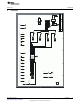
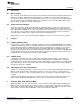
SLVU498 – July 2011 Submit Documentation Feedback 1 Copyright © 2011, Texas Instruments Incorporated DRV8833 1 nFAULT PCB1 D1 R9 499 1 4 3 2 1 GND R5 .15 AISEN Header4 J2 1 AOUT1 AOUT2 BOUT2 BOUT1 VDD JP5 1 GND R6 .
PCB www.ti.
Connectors www.ti.com 4 Connectors 4.1 Motor Outputs The connector J2 should be connected to the motor terminals. Each pin in this terminal is labeled on the EVM itself as AOUT1, AOUT2, BOUT1 and BOUT2. The polarity of these connections will affect the direction of the motor in the case of a brushed DC motor. In case of a stepper motor, one winding should be connected to AOUT1 and AOUT2, while the other should be connected to the outputs BOUT1 and BOUT2. Refer the datasheet for further information. 4.
LED (D1) 7 www.ti.com LED (D1) The diode D1 indicates the status of the nFAULT signal. When there is a FAULT condition on the DRV8833, this LED lights up. The two possible fault conditions are over current and over temperature. Refer to the schematic / datasheet for more information. 8 Test Points Kelvin connections are provided for all pins of DRV8833. They are appropriately labeled on the EVM.
Evaluation Board/Kit Important Notice Texas Instruments (TI) provides the enclosed product(s) under the following conditions: This evaluation board/kit is intended for use for ENGINEERING DEVELOPMENT, DEMONSTRATION, OR EVALUATION PURPOSES ONLY and is not considered by TI to be a finished end-product fit for general consumer use. Persons handling the product(s) must have electronics training and observe good engineering practice standards.
IMPORTANT NOTICE Texas Instruments Incorporated and its subsidiaries (TI) reserve the right to make corrections, modifications, enhancements, improvements, and other changes to its products and services at any time and to discontinue any product or service without notice. Customers should obtain the latest relevant information before placing orders and should verify that such information is current and complete.