
Datasheet


DRV8825
www.ti.com
SLVSA73E –APRIL 2010–REVISED AUGUST 2013
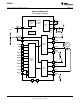
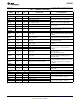
Table 1. TERMINAL FUNCTIONS
EXTERNAL COMPONENTS
NAME PIN I/O
(1)
DESCRIPTION
OR CONNECTIONS
POWER AND GROUND
GND 14, 28 - Device ground
VMA 4 - Bridge A power supply
Connect to motor supply (8.2 - 45 V). Both
pins must be connected to same supply.
VMB 11 - Bridge B power supply
Bypass to GND with a 0.47-μF 6.3-V ceramic
V3P3OUT 15 O 3.3-V regulator output
capacitor. Can be used to supply VREF.
CP1 1 IO Charge pump flying capacitor
Connect a 0.01-μF 50-V capacitor between
CP1 and CP2.
CP2 2 IO Charge pump flying capacitor
Connect a 0.1-μF 16-V ceramic capacitor and
VCP 3 IO High-side gate drive voltage
a 1-MΩ resistor to VM.
CONTROL
Logic high to disable device outputs and
nENBL 21 I Enable input indexer operation, logic low to enable. Internal
pulldown.
Logic high to enable device, logic low to enter
nSLEEP 17 I Sleep mode input
low-power sleep mode. Internal pulldown.
Rising edge causes the indexer to move one
STEP 22 I Step input
step. Internal pulldown.
Level sets the direction of stepping. Internal
DIR 20 I Direction input
pulldown.
MODE0 24 I Microstep mode 0
MODE0 - MODE2 set the step mode - full,
MODE1 25 I Microstep mode 1 1/2, 1/4, 1/8/ 1/16, or 1/32 step. Internal
pulldown.
MODE2 26 I Microstep mode 2
Low = slow decay, open = mixed decay,
DECAY 19 I Decay mode high = fast decay.
Internal pulldown and pullup.
Active-low reset input initializes the indexer
nRESET 16 I Reset input logic and disables the H-bridge outputs.
Internal pulldown.
AVREF 12 I Bridge A current set reference input Reference voltage for winding current set.
Normally AVREF and BVREF are connected
to the same voltage. Can be connected to
BVREF 13 I Bridge B current set reference input
V3P3OUT.
STATUS
nHOME 27 OD Home position Logic low when at home state of step table
Logic low when in fault condition (overtemp,
nFAULT 18 OD Fault
overcurrent)
OUTPUT
ISENA 6 IO Bridge A ground / Isense Connect to current sense resistor for bridge A.
ISENB 9 IO Bridge B ground / Isense Connect to current sense resistor for bridge B.
AOUT1 5 O Bridge A output 1
Connect to bipolar stepper motor winding A.
Positive current is AOUT1 → AOUT2
AOUT2 7 O Bridge A output 2
BOUT1 10 O Bridge B output 1
Connect to bipolar stepper motor winding B.
Positive current is BOUT1 → BOUT2
BOUT2 8 O Bridge B output 2
(1) Directions: I = input, O = output, OZ = tri-state output, OD = open-drain output, IO = input/output
Copyright © 2010–2013, Texas Instruments Incorporated Submit Documentation Feedback 3
Product Folder Links: DRV8825