
Datasheet


DRV8803 DRV8804/06
DRV8805
The Windows Application
www.ti.com
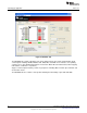
Figure 14. GPIO Control Signals
nENBL – Control appears on all three devices. Toggling it LO (red) enables the chip, and toggling it HI
(green) disables the chip. Automatically toggles in correspondence to the Enable Button on all three chips
(See motor control).
Reset – Control appears on all three devices. Must be toggled LO (red) in order for the device to operate.
If toggled HI (green) and then LO (red) it resets the chip. Automatically toggles in correspondence to
Reset Button (See motor control).
INx – Control appears on the DRV8803 device. Toggling HI (green) sets PWM of input X to a duty cycle of
100%. Toggling LO (red) sets PWM of input X to a duty cycle of 0%. Automatically toggles in
correspondence to INx sliders and % duty cycle combo boxes (See PWM control). The pin will show
orange if the user selects anything other than a 0% of 100% duty cycle. If user clicks pin to toggle from
orange the pin will go LO (red).
STEP – Control appears on the DRV8805 device. Toggling LO (red) and then HI (green) will enable a
bipolar stepper motor to step once. Toggles in correspondence to Pulse 1 Step button (See speed
control).
DIR – Control appears on the DRV8805 device. Toggling HI (green) will allow the motor to operate in the
forward direction, while toggling LO (red) will allow the motor to operate in the reverse direction.
Automatically toggles in correspondence to Motor Direction radio buttons (See Motor Control)
SMx – Control appears on the DRV8805 device. Toggling these pins selects the mode that the motor is
operating in (microstepping – full, half, wave mode, reverse). The following look up table shows the
combinations and their results:
16
SLVU574A–September 2011–Revised June 2012
Submit Documentation Feedback
Copyright © 2011–2012, Texas Instruments Incorporated