
Datasheet


MSP430
Low-Pass
Filter
DRV8662
SDA
SCL
I C
2
www.ti.com
General Operation
3.3.4 I
2
C Input Mode
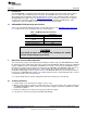
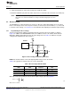
Figure 6. I
2
C Input Mode
This mode uses a serial bus protocol (I
2
C) to transfer waveform data points digitally from an external I
2
C
source to the MSP430. Using the I
2
C terminal block, the MSP430 receives the I
2
C values and decodes
them to produce a PWM waveform.
1. Update the firmware on the MSP430 for I
2
C input mode. To update the firmware, download Code
Composer Studio (or a third-party MSP430 IDE) and connect the DRV8662EVM SpyBiWire to the
computer. The TI website offers an MSP430 USB-to-JTAG hardware interface (MSP-FET430UIF) for
updating and debugging MSP430 code, and the DRV8662EVM kit includes a JTAG-to-SpyBiWire
adapter for connecting the JTAG interface to the DRV8662EVM SpyBiWire connector.
2. Connect the SDA, SCL, and GND signals to the I
2
C header.
3. Enable the power supply.
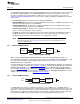
3.3.5 Single-Ended and Differential Inputs
The input signal can either be a single-ended or differential source. Follow the instructions below for each
input source.
• Single-ended input: Connect the input source to the positive terminal of EXTIN (+) and ground of the
source to the negative terminal of EXTIN (–).
• Differential input: The input should be applied differentially across the EXTIN header.
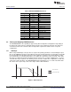
If using a PWM waveform, it is recommended to use a PWM signal greater than 20 kHz and vary the duty
cycle to produce a sine wave.
3.4 Programming the MSP430
The MSP430 can be reprogrammed to create unique functionality and custom haptic effects. To update
the firmware, the following tools and software are required:
1. An integrated development environment (IDE) for the MSP430, such as Code Composer Studio (CCS)
(free) or the IAR Embedded Workbench Kickstart Edition.
2. The MSP-FET430UIF USB Debugging Hardware Interface.
3. The MSP-JTAG2SBW JTAG to Spy-Bi-Wire adapter (included in the DRV8662EVM kit).
To reprogram the MSP430, follow this procedure:
1. Connect the DRV8662EVM to a computer using the MSP-FET430UIF and the JTAG to Spy-Bi-Wire
adapter. The Spy-Bi-Wire adapter should be attached to the small 6-pin header (SBW) on the
DRV8662EVM.
2. Start the MSP430 IDE.
3. Ensure that the IDE is configured for the MSP430G2553.
9
SLOU319A–August 2011–Revised December 2012 DRV8662 Piezo Haptics Driver Evaluation Module
Submit Documentation Feedback
Copyright © 2011–2012, Texas Instruments Incorporated