
Datasheet
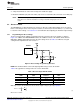


R =
EXT
K
V
REF
LIM
I
- R
INT
General Operation
www.ti.com
The maximum boost output voltage is 105 V. VBST should be programmed to a value 5 V greater than the
largest peak voltage expected in the system to allow adequate amplifier headroom. Because the
programming range for the boost voltage extends to 105 V, the current through the resistor divider can
become significant. The sum of the feedback resistors R1 and R2 should be greater than 500 kΩ.
NOTE: When the feedback resistor values are greater than 1 MΩ, PCB contamination may cause
boost voltage inaccuracies. Be sure to keep the board clean from excess solder and flux
when modifying the board.
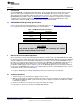
Table 4 lists typical resistor values for common boost voltage levels.
Table 4. Boost Voltage and Gain Settings
V
O
(peak-to-
R1 R2 GAIN1 GAIN0 VBST peak)
402k 18.2k 0 0 30 50
392k 9.76k 0 1 55 100
768k 13k 1 0 80 150
768k 9.76k 1 1 105 200
3.2.2 Programming the Boost Current Limit
The peak inductor current is set by resistor R3 (R
EXT
). The current limit is not a safety mechanism, but the
highest value current the inductor will see each cycle. The inductor must be capable of handling this
programmed limit during normal operation. The relationship of R
EXT
to I
LIM
is approximated by Equation 2:
(2)
where I
LIM
is the current limit set by R
EXT,
K = 10500, V
REF
= 1.35 V and R
INT
= 60 Ω.
3.2.3 Boost Inductor Selection
Inductor selection plays a critical role in the performance of the DRV8662. The range of recommended
inductor values is 3.3 µH to 22 µH. When a larger inductance is chosen, the DRV8662 boost converter will
automatically run at a lower switching frequency and incur less switching losses; however, the larger
inductors may also have a higher equivalent series resistance (ESR), which will increase the parasitic
inductor losses. Smaller inductances generally have higher saturation currents; therefore, they are better
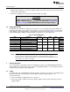
suited for maximizing the output current of the boost converter. Table 5 lists several sample inductors that
provide adequate performance.
Table 5. Inductor Selection
Manufacturer Part Number DCR (Ω) Inductance (µH) I
SAT
(A) R
EXT
(Ω) I
LIM
(A)
Coilcraft LPS4018-332MLB 0.080 3.3 1.9 7.32k 1.9
Coilcraft LPS4018-472MLB 0.125 4.7 1.8 7.5k 1.8
TDK VLS3012T-3R3M1R3 0.100 3.3 1.5 9.31k 1.5
3.2.4 Boost Capacitor Selection
The boost output voltage may be programmed as high as 105 V. A capacitor must have a voltage rating
equivalent to the boost output voltage or higher. A 250-V rated 100-nF capacitor of X5R or X7R type is
recommended for a boost converter voltage of 105 V. The selected capacitor should have a minimum
derated capacitance of 50 nF.
6
DRV8662 Piezo Haptics Driver Evaluation Module SLOU319A–August 2011–Revised December 2012
Submit Documentation Feedback
Copyright © 2011–2012, Texas Instruments Incorporated