
Datasheet


www.ti.com
1 DRV8662EVM............................................................................................................... 1
2 Boost Voltage Programming Resistors................................................................................... 5
3 MSP430 PWM Input Mode ................................................................................................ 7
4 External PWM Input Mode................................................................................................. 7
5 External Analog Input Mode ............................................................................................... 8
6 I
2
C Input Mode............................................................................................................... 9
7 Filter Response ............................................................................................................ 10
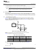
8 First-Order Input Filter .................................................................................................... 11
9 First-Order Frequency Response ....................................................................................... 11
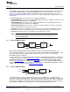
10 Second-Order Input Filter ................................................................................................ 12
11 Second-Order Filter Frequency Response............................................................................. 12
12 Second-Order, Single-Ended Filter ..................................................................................... 13
13 Second-Order, Differential Filter......................................................................................... 13
14 Single-Ended Input with Dummy Filter ................................................................................. 13
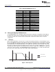
15 Dummy Filter Waveform.................................................................................................. 14
16 EVM Top X-Ray ........................................................................................................... 16
17 EVM Top Layer ............................................................................................................ 17
18 EVM Layer 2 ............................................................................................................... 17
19 EVM Layer 3 ............................................................................................................... 18
20 EVM Bottom Layer ........................................................................................................ 18
List of Tables
1 EVM Operating Specifications............................................................................................. 3
2 Default EVM Modes ........................................................................................................ 4
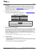
3 Boost Voltage with R4 and R5 ............................................................................................ 5
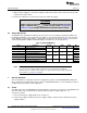
4 Boost Voltage and Gain Settings ......................................................................................... 6
5 Inductor Selection........................................................................................................... 6
6 DRV8662EVM MSP430 Pinout.......................................................................................... 10
7 Piezo Actuator Selection ................................................................................................. 14
2
DRV8662 Piezo Haptics Driver Evaluation Module SLOU319A–August 2011–Revised December 2012
Submit Documentation Feedback
Copyright © 2011–2012, Texas Instruments Incorporated