
Datasheet


R13
3.3 kW
R6
0 W
R18
2.7 kW
C13
0.047 Fm
C8
0.047 Fm
C4
0.1 Fm
R14
3.3 kW
R7
3.3 kW
R17
2.7 kW
C14
0.047 Fm
C9
0.047 Fm
C5
0.1 Fm
IN-
PWM+
IN+
R21
6.5 kW
R9
6.5 kW
EN
www.ti.com
General Operation
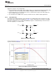
3.5.1.4 Second-Order Filter, Single-Ended
Second-order filters take longer to settle than first-order filters. With differential inputs, the inverting and
noninverting inputs settle at the same time. With a single-ended input, they do not. This characteristic is
seen in the waveforms (refer to Figure 12 and Figure 13).
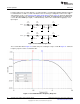
Figure 12. Second-Order, Single-Ended Filter Figure 13. Second-Order, Differential Filter
To avoid this issue, a dummy filter may be connected to the unused input; the filter input should then be
tied to the DRV8662 enable (EN) signal through a resistor divider, as seen in Figure 14. When the
DRV8662 is enabled, the enable (EN) signal charges this dummy filter.
Figure 14. Single-Ended Input with Dummy Filter
13
SLOU319A–August 2011–Revised December 2012 DRV8662 Piezo Haptics Driver Evaluation Module
Submit Documentation Feedback
Copyright © 2011–2012, Texas Instruments Incorporated