
Datasheet


f
IN
f f-
S IN
f
S
f + f
S IN
First-order filter
Second-order filter
General Operation
www.ti.com
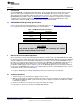
Table 6 lists the MSP430G2553 pinout on the DRV8662EVM.
Table 6. DRV8662EVM MSP430 Pinout
Pin No. Label Description
1 P1.1 GAIN0
2 P1.2 GAIN1
3 P1.3 EN / ACTIVE
12 P3.2 PWM+
13 P3.3 PWM–
17 P2.5 TRIG (Pushbutton)
21 P1.6/SCL I
2
C Clock
22 P1.7/SDA I
2
C Data
23 SBWTDIO Spy-Bi-Wire Data
24 SBWTCK Spy-Bi-Wire Clock
25 P2.7 GAIN1 FET Control
26 P2.6 GAIN0 FET Control
27 AVSS Analog Ground
28 DVSS Digital Ground
29 AVCC Analog Supply
30 DVCC Digital Supply
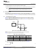
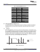
3.5 Filtering and Adapting PWM Waveforms
The DRV8662EVM has the capability to support many different input filter configurations. Depending on
the input mode, input frequency and input voltage the filter can be adapted to attenuate any undesired
out-of-band content. This section describes the input filter requirements and the various respective
configurations.
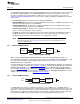
3.5.1 PWM Input
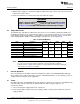
When using a PWM input, a low-pass filter is required. The primary parameters for determining the input
filter are the PWM input frequency and sample rate. Because haptic waveforms are typically less than 500
Hz, the input filter must attenuate frequencies above 500 Hz. For samples rates above 20 kHz, a simple
first-order RC filter is recommended; however, for sample rates much lower (such as 8 kHz), a first-order
filter may not sufficiently attenuate the high-frequency content. Thus, for lower sampling rates, a second-
order RC filter may be required. The following sections describe example filter configurations for both first-
order and second-order filters. The DRV8662EVM default configuration uses a second-order, differential
filter, but it can be replaced by a first-order, single-ended or differential filter.
Figure 7. Filter Response
10
DRV8662 Piezo Haptics Driver Evaluation Module SLOU319A–August 2011–Revised December 2012
Submit Documentation Feedback
Copyright © 2011–2012, Texas Instruments Incorporated