
Datasheet

EVM
RES
PRN
SW2
EVM
ON
OFF
SW
www.ti.com
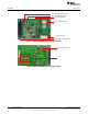
Connectors and Switches
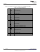
Table 3. Analog and Digital I/O (continued)
Pin# Name Description
A9 CTLUH Pre-driver parallel input
B9 RES Reset output
A10 PRN Watchdog timer pulse input
B10 FAULT Diagnosis output
A11 OVCR Overcurrent reset input (not used)
B11 NC No connection
A12 CANRX CAN digital receive data output (not used)
B12 CANTX CAN digital transmit data input (not used)
A13 NC No Connection
B13 PTV1 Phase output 1
A14 PTV2 Phase output 2
B14 PTV3 Phase output 3
A15 GND Ground
B15 ALV Motor current sense amp output
A16 GND Ground
B16 VCC 5-V VCC supply output
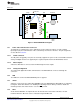
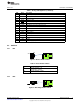
2.2 Switches
2.2.1 SW1
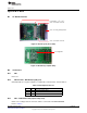
Figure 4. Device Enable Switch
Table 4. Device Enable Switch
Switch Description
ON DRV3204 ENABLE = VB
DRV3204-Q1 is enabled
OFF DRV3204 ENABLE = OPEN
DRV3204-Q1 is disabled
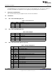
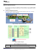
2.2.2 SW2
Figure 5. Watchdog Disable Switch
5
SLVU844–February 2013 DRV3204-Q1 EVM
Submit Documentation Feedback
Copyright © 2013, Texas Instruments Incorporated