
User manual

www.ti.com
DRV2605 Demonstration Program
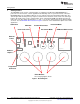
2.1 Demo Mode
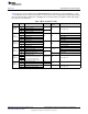
Table 2 lists the effects preloaded on the DRV2605EVM-CT. The modes are selected using the “+” and
“–“ mode buttons in the center of the board. The current mode can be identified by the white LEDs directly
above the mode buttons. Buttons B1 to B4 trigger the effects listed in the description column and change
based on the selected mode.
Table 2. Mode and Effects Table
Waveform
Mode Button Description Actuator Interface
Location
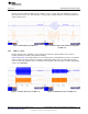
B1 Click + Ramp Down
ERM
B2 Ramp Up + Pulsing
Mode Off
ROM
Internal trigger (I
2
C)
LEDs Off
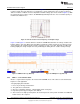
B3 Click + Ramp Down
LRA
B4 Ramp Up + Pulsing
B1 SharpClick_100 Internal trigger
B2 StrongClick_60 + Release External edge trigger
Mode 4
ERM ROM
LED M4 On
B3 SoftBump_100 Internal trigger
B4 DoubleClick_100 External level trigger
B1 SharpTick2_80 Internal trigger
B2 StrongClick_100 + Release External edge trigger
Mode 3
LRA ROM
LED M3 On
B3 SoftBump_100 Internal trigger
B4 DoubleClick_100 External level trigger
B1 LRA auto-resonance on RTP
LRA
B2 LRA auto-resonance off µController PWM
Mode 2
LED M2 On
B3 ERM buzz alert (closed loop) RTP
ERM
B4 ERM buzz alert (open loop) ROM Internal trigger
B1
Concentration game
The board displays a pattern using the
B2
Mode 1
effect buttons. See how many times ERM and LRA ROM
Internal trigger (I
2
C)
LED M1 On
B3
you can repeat the pattern as it
increases by one effect each time.
B4
B1 Audio-to-haptics enable ERM
External analog
Audio-to-haptics
source
B2 Audio-to-haptics enable LRA
Mode 0
LED M0 On
B3 Exit A2H, click, return to A2H
ERM and LRA ROM
Internal trigger (I
2
C)
B4 Exit A2H, buzz, return to A2H
7
SLOU348B–January 2013–Revised March 2014 DRV2605EVM-CT ERM and LRA Haptic Driver Evaluation Kit
Submit Documentation Feedback
Copyright © 2013–2014, Texas Instruments Incorporated