
User manual

www.ti.com
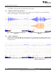
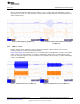
24 DRV2605 Filtered Waveform ............................................................................................. 21
25 Measuring the DRV2605 Output Signal With an Analog Low-Pass Filter .......................................... 21
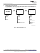
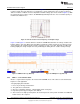
26 LaunchPad Programmer Connection.................................................................................... 22
27 X-Ray Top View ............................................................................................................ 25
28 Top Copper ................................................................................................................. 25
29 Layer 2 Copper ............................................................................................................. 26
30 Layer 3 Copper ............................................................................................................. 26
31 Bottom Copper.............................................................................................................. 27
List of Tables
1 Jumper Descriptions......................................................................................................... 5
2 Mode and Effects Table..................................................................................................... 7
3 DRV2605 Library Table ................................................................................................... 12
4 Binary Counting Modes.................................................................................................... 15
5 Hardware Overview ........................................................................................................ 16
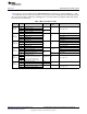
6 MSP430 Pinout ............................................................................................................. 23
3
SLOU348B–January 2013–Revised March 2014 DRV2605EVM-CT ERM and LRA Haptic Driver Evaluation Kit
Submit Documentation Feedback
Copyright © 2013–2014, Texas Instruments Incorporated