
User manual

JP1
VDD
DRV2605
EN
IN/TRIG
GND
OUT+
OUT-
MSP430
PWM/
GPIO
P3.1
R8
EN PWM
SDA
SCL
SDA
SCL
C11
AUDIO
R40, 0Q
R41, NP
SDA SCL
R43, 0Q
Hardware Configuration
www.ti.com
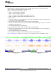
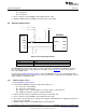
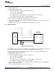
4.7 Audio-to-Haptics Input
Figure 21. Audio-to-Haptics Input
The DRV2605 audio-to-haptics feature converts an audio signal to a corresponding haptics waveform.
This can be used to simulate bass in music, or use the audio track of a game to produce haptic effects.
To use audio-to-haptics:
1. Apply an analog line-out audio signal (not PWM) to the AUDIO jack on the left side of the board. The
tip of the inserted male audio plug is applied to the IN/TRIG pin of the DRV2605. See Figure 21.
NOTE: To get the best performance using a headphone out, the user may need to adjust the
volume, so that the input signal is near, but does not exceed 1.8 V
peak
.
2. In demo mode, select mode 0 (00001’b) using the increment mode button (“+”).
3. In mode 0, press either button B1 or B2 to enable the DRV2605 audio-to-haptics. Buttons B3 and B4
switch to internal trigger mode, play a ROM library effect, and then switch back to audio-to-haptics
mode.
• B1 – Audio-to-haptics using ERM
• B2 – Audio-to-haptics using LRA
• B3 – Switch to internal trigger and play library click effect
• B4 – Switch to internal trigger and play library buzz effect
4. Play music and feel the vibrations of the actuator.
NOTE: Some audio signals are too large or too small and the volume must be adjusted. Adjust
appropriately so that the maximum input voltage is 1.8 V and the bass of the input signal can
be felt on the actuator. The audio input minimum and maximum thresholds can be adjusted
using I
2
C. See the datasheet for more details.
20
DRV2605EVM-CT ERM and LRA Haptic Driver Evaluation Kit SLOU348B–January 2013–Revised March 2014
Submit Documentation Feedback
Copyright © 2013–2014, Texas Instruments Incorporated