
User manual

JP1
VDD
DRV2605
EN
IN/TRIG
GND
OUT+
OUT-
MSP430
PWM/
GPIO
P3.1
R8
EN PWM
SDA
SCL
SDA
SCL
C11
AUDIO
R40, 0Q
R41, NP
SDA SCL
R43, 0Q
Hardware Configuration
www.ti.com
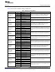
• B2 - ERM mode
• B3 - LRA mode
• B4 - No function
3. Choose either the on-board ERM or LRA using button B1 or B2.
4. Apply the PWM signal to the PWM test point at the top of the board.
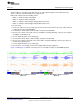
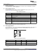
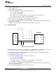
4.5 External Trigger Control
Figure 19. External Trigger Control
JP1 PWM Source
Shorted MSP430
Open External GPIO using PWM test point
The DRV2605 internal waveform sequencer can be triggered by controlling the IN/TRIG pin. There are
two external trigger options: edge trigger and level trigger. See the datasheet for more information on
these input trigger modes.
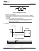
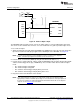
In mode 0 in the Additional Hardware Modes section, the DRV2605 can be set in external trigger mode,
and then triggered by using the trigger button control on button B4, or alternatively by applying an external
trigger signal to the PWM test point.
4.5.1 MSP430 Trigger Control
1. Enter Additional Hardware Modes.
2. Select Mode 0 (00000’b) using the increment mode button (“+”).
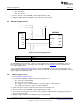
• B1 - Select the on-board ERM
• B2 - Select the on-board LRA
• B3 - Trigger select (1 = Internal trigger, 2 = External edge, 3 = External level)
• B4 - Trigger the waveform sequence using the MSP430
3. Fill the waveform sequencer with waveforms using the external I
2
C port.
4. Choose either the on-board ERM or LRA using buttons B1 or B2.
5. Select either external edge (2) or external level (3) trigger using button B3. The trigger type appears in
binary on the mode LEDs.
6. Apply the trigger signal to the IN/TRIG pin by pressing button B4.
18
DRV2605EVM-CT ERM and LRA Haptic Driver Evaluation Kit SLOU348B–January 2013–Revised March 2014
Submit Documentation Feedback
Copyright © 2013–2014, Texas Instruments Incorporated