User's Guide SLOU348B – January 2013 – Revised March 2014 DRV2605EVM-CT ERM and LRA Haptic Driver Evaluation Kit The DRV2605 is a haptic driver designed for linear resonant actuators (LRA) and eccentric rotating mass (ERM) motors.
www.ti.com 7 8 9 Contents Getting Started ............................................................................................................... 4 1.1 Evaluation Module Operating Parameters ...................................................................... 5 1.2 Quick Start Board Setup ........................................................................................... 5 DRV2605 Demonstration Program ......................................................................................
www.ti.com 24 DRV2605 Filtered Waveform ............................................................................................. 21 25 Measuring the DRV2605 Output Signal With an Analog Low-Pass Filter .......................................... 21 26 LaunchPad Programmer Connection .................................................................................... 22 27 X-Ray Top View ............................................................................................................
Getting Started 1 www.ti.com Getting Started The DRV2605 can be used as a demonstration or evaluation tool. When the DRV2605EVM-CT is powered on for the first time, a demo application automatically starts. To power the board, connect the DRV2605EVM-CT to an available USB port on your computer using the included mini-USB cable. The demo begins with a board power-up sequence, and then enters the demo effects mode.
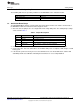
Getting Started www.ti.com 1.1 Evaluation Module Operating Parameters The following table lists the operating conditions for the DRV2605 on the evaluation module. 1.2 Parameter Specification Supply voltage range 2.5 to 5.5 V Power-supply current rating 400 mA Quick Start Board Setup The DRV2605EVM-CT firmware contains haptic waveforms which showcase the features and benefits of the DRV2605. Follow the instructions below to begin the demo. 1.
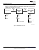
DRV2605 Demonstration Program 2 www.ti.com DRV2605 Demonstration Program The DRV2605EVM-CT contains a microcontroller and embedded software to control the DRV2605. There are three sets of modes accessible by pressing and holding the “+” button. Follow the instructions in the following sections to access the effects in each set. Hold for 3 s + Demo Mode Modes Mode OFF Mode 4 Mode 3 + . . Mode 0 Hold for 3 s ROM Library Mode + Binary Counting Mode Modes* Mode 0 Mode 1 Mode 2 . .
DRV2605 Demonstration Program www.ti.com 2.1 Demo Mode Table 2 lists the effects preloaded on the DRV2605EVM-CT. The modes are selected using the “+” and “–“ mode buttons in the center of the board. The current mode can be identified by the white LEDs directly above the mode buttons. Buttons B1 to B4 trigger the effects listed in the description column and change based on the selected mode. Table 2.
DRV2605 Demonstration Program 2.2 www.ti.com Description of the Demo Modes The following sections describe each demo mode in more detail. 2.2.1 Mode Off – Haptics Effect Sequences Mode Off contains a set of haptic sequences that combine a series of haptic effects. The two following effects show combinations of clicks, ramps, and pulses. Figure 3. ERM Click and Ramp-Down Waveform (Button 1) 2.2.2 Figure 4.
DRV2605 Demonstration Program www.ti.com 2.2.3 Mode 3 – LRA Clicks Mode 3 shows two different LRA click styles. Button 1 shoes a single sharp click and Button 2 shows a click and release effect. The click and release effect provides a haptic waveform on both the button press and the button release. Figure 7. LRA SharpTick2_80 (Button 1) 2.2.4 Figure 8.
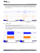
DRV2605 Demonstration Program www.ti.com Acceleration (G) The reason for higher acceleration can be seen in Figure 11. The LRA has a very-narrow operating frequency range due to the properties of a spring-mass system. Furthermore, the resonance frequency drifts over various conditions such as temperature and drive voltage (the effects shown in Figure 11). With the smart loop auto-resonance feature, the DRV2605 dynamically tracks the exact resonant frequency to maximize the vibration force.
DRV2605 Demonstration Program www.ti.com 2.2.6 Mode 0 – Audio-to-Haptics Audio-to-haptics is a unique feature that converts an audio signal to haptics. Take audio from music, games, or movies and automatically create haptic effects.
DRV2605 Demonstration Program 2.3 www.ti.com ROM Library Mode ROM library effects can be accessed by holding the "+" button until the mode LEDs flash and colored LEDs flash once. Once in "Library Mode," the DRV2605 embedded ROM effects can be accessed in sequential order. For example, with all mode LEDs off, B1 is waveform 1, B2 is waveform 2, and so on. Then when mode LED M0 is on, B1 is waveform 5, B2 is waveform 6, and so on.
DRV2605 Demonstration Program www.ti.com 2.4 ROM Library Effects List Below is a description of the 123 waveforms embedded in the DRV2605.
Additional Hardware Modes 3 www.ti.com Additional Hardware Modes Additional modes are available on the DRV2605EVM-CT that provide increased board control and functionality. The additional modes are not available in “demo” mode, but can be accessed by switching to “binary counting mode”. In “binary counting mode,” the mode LEDs count in binary (32 modes) rather than in “demo” mode format (only six modes including off). 3.
Additional Hardware Modes www.ti.com 3.3 Binary Counting Modes Table 4 lists the modes available in “binary counting mode”. Table 4.
Hardware Configuration 4 www.ti.com Hardware Configuration The DRV2605EVM-CT is flexible and can be used to completely evaluate the DRV2605. The following sections list the various hardware configurations. 4.1 Input and Output Overview The DRV2605EVM-CT allows complete evaluation of the DRV2605 though test points, jacks, and connectors. Table 5 gives a brief description of the hardware. Table 5.
Hardware Configuration www.ti.com 4.3 Using an External Actuator OUT- OUT+ OUT 470pF 100k 100k 470pF From DRV2605 Figure 17. Terminal Block and Test Points The DRV2605EVM-CT can be used with an external actuator. Follow the instructions below to attach an actuator to the "OUT" terminal block. 1. Remove jumpers JP3 and JP4, which disconnects the on-board actuators from the DRV2605. 2. Attach the positive and negative leads of the actuator to the green “OUT” terminal block keeping in mind polarity.
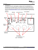
Hardware Configuration www.ti.com • B2 - ERM mode • B3 - LRA mode • B4 - No function 3. Choose either the on-board ERM or LRA using button B1 or B2. 4. Apply the PWM signal to the PWM test point at the top of the board. 4.5 External Trigger Control AUDIO R40, 0Q R41, NP EN PWM R43, 0Q MSP430 DRV2605 C11 R8 P3.1 PWM/ GPIO EN OUT+ IN/TRIG GND JP1 VDD SDA SDA SCL SCL OUT- SDA SCL Figure 19.
Hardware Configuration www.ti.com 4.5.2 External Source Trigger Control 1. Remove jumper JP1. 2. Enter Additional Hardware Modes. 3. Select mode 0 (00000’b) using the increment mode button (“+”). • B1 - Select the on-board ERM • B2 - Select the on-board LRA • B3 - Trigger Select (1 = Internal trigger, 2 = External edge, and 3 = External level) • B4 - Trigger the waveform sequence using the MSP430 4. Fill the waveform sequencer with waveforms using the external I2C port. 5.
Hardware Configuration 4.7 www.ti.com Audio-to-Haptics Input AUDIO R40, 0Q R41, NP EN PWM R43, 0Q DRV2605 C11 MSP430 R8 P3.1 PWM/ GPIO EN OUT+ IN/TRIG GND JP1 VDD SDA SDA SCL SCL SDA OUT- SCL Figure 21. Audio-to-Haptics Input The DRV2605 audio-to-haptics feature converts an audio signal to a corresponding haptics waveform. This can be used to simulate bass in music, or use the audio track of a game to produce haptic effects. To use audio-to-haptics: 1.
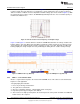
Measurement and Analysis www.ti.com 5 Measurement and Analysis The DRV2605 uses PWM modulation to create the output signal for both ERM and LRA actuators. To measure and observe the DRV2605 output waveform, connect an oscilloscope or other measurement equipment to the filtered output test points, “OUT+” and “OUT–". OUT- OUT+ OUT 470pF 100k 100k 470pF From DRV2605 Figure 22.
MSP430 Firmware 6 www.ti.com MSP430 Firmware The MSP430 firmware on the DRV2605EVM-CT can be modified or reprogrammed to create new haptic effects or behaviors. Find the latest firmware source code and binaries on www.ti.com. Follow these instructions to modify or reprogram the DRV2605EVM-CT: 1.
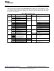
MSP430 Firmware www.ti.com 6.1 MSP430 Pinout The DRV2605EVM-CT contains a MSP430G2553 low-cost microcontroller, which controls the board and contains sample haptic effects. The pinout for the microcontroller can be found in Table 6. Table 6. MSP430 Pinout NO. NAME 1 P1.1 Green LED DESCRIPTION 2 P1.2 Yellow LED 3 P1.3 Blue LED 4 P1.4 VREF+ 5 P1.5 Audio-to-haptics 6 P3.1 Enable 7 P3.0 Actuator mode selection 8 NC 9 P2.0 Button 1 10 P2.1 Button 2 11 P2.2 Button 3 12 P3.
Schematic Schematic +3.3 V U3 Vbat 0.0 0603 R4 C7 + DNP 0603 1.0 µF / 6.3 V 0402 GND GND FB2 1.5 kΩ 0402 600 Ω / 2 A 0805 GND GND BTN0 BTN1 BTN4 R21 R22 R23 R24 R25 DNP 0402 DNP 0402 DNP 0402 DNP 0402 DNP 0402 DNP 0402 M3 M2 M1 M0 R15 R16 R17 R18 R19 249 0402 249 0402 249 0402 249 0402 249 0402 White 0603 EXT INPUT TP1 CAPTOUCH RESISTORS GND FB1 Black ENIN Orange White 0603 BTN2 WLED0 BTN3 WLED1 BTN4 JP1 GND NC P3.1 Vbat SBYBIWIRE P1.
Layout www.ti.com 8 Layout Figure 27. X-Ray Top View spacer Figure 28.
Layout www.ti.com Figure 29. Layer 2 Copper spacer Figure 30.
Layout www.ti.com Figure 31.
Bill of Materials 9 www.ti.
Bill of Materials www.ti.com ITEM MANU PART NUMBER QTY REF DESIGNATORS VENDOR PART NUMBER DESCRIPTION MANUFACTURER 21 RMCF0402ZT0R00 5 R8, R32, R33, R34, R36 RMCF0402ZT0R00CT ZERO OHM JUMPER SMT 0402 0 OHM 1/16W,5% ROHS STACKPOLE ELECTRONICS 22 RC0402FR-07511RL 5 R9, R11, R12, R13, R14 311-511LRCT-ND RESISTOR SMD0402 THICK FILM 511 OHMS 1% 1/16W ROHS YAGEO 23 ERJ-2GEJ152 1 R26 RESISTOR,SMT,0402,THICK FILM,5%,1/16W,1.
Bill of Materials ITEM 40 (1) MANU PART NUMBER www.ti.com QTY REF DESIGNATORS VENDOR PART NUMBER DESCRIPTION MANUFACTURER ELV1036 - - - Alternate ACTUATOR – LINEAR VIBRATOR, 2VRMS AAC 42 3-5-468MP 1 - 3M9724-ND TAPE TRANSFER ADHESIVE 3" X 5YD 3M 43 2-5-4466W 1 - 3M9962-ND TAPE POLY FOAM 2" x 5YD 3M 44 TestPoint_SMDSquare_2.0mm 2 LRA_OUT+,LRA_OUT– TESTPOINT SMD SQUARE 2.
Revision History www.ti.com Revision History Changes from Original (January 2013) to A Revision .................................................................................................... Page • • • Added a diagram of the different modes of the DRV2605EVM ..................................................................... 6 Changed the capacitance of C2 to 1 µF / 16 V ......................................................................................
ADDITIONAL TERMS AND CONDITIONS, WARNINGS, RESTRICTIONS, AND DISCLAIMERS FOR EVALUATION MODULES Texas Instruments Incorporated (TI) markets, sells, and loans all evaluation boards, kits, and/or modules (EVMs) pursuant to, and user expressly acknowledges, represents, and agrees, and takes sole responsibility and risk with respect to, the following: 1. User agrees and acknowledges that EVMs are intended to be handled and used for feasibility evaluation only in laboratory and/or development environments.
RADIO FREQUENCY REGULATORY COMPLIANCE INFORMATION FOR EVALUATION MODULES Texas Instruments Incorporated (TI) evaluation boards, kits, and/or modules (EVMs) and/or accompanying hardware that is marketed, sold, or loaned to users may or may not be subject to radio frequency regulations in specific countries. General Statement for EVMs Not Including a Radio For EVMs not including a radio and not subject to the U.S.
Canada Industry Canada Compliance (French) Cet appareil numérique de la classe A ou B est conforme à la norme NMB-003 du Canada Les changements ou les modifications pas expressément approuvés par la partie responsable de la conformité ont pu vider l’autorité de l'utilisateur pour actionner l'équipement. Concernant les EVMs avec appareils radio Le présent appareil est conforme aux CNR d'Industrie Canada applicables aux appareils radio exempts de licence.
IMPORTANT NOTICE Texas Instruments Incorporated and its subsidiaries (TI) reserve the right to make corrections, enhancements, improvements and other changes to its semiconductor products and services per JESD46, latest issue, and to discontinue any product or service per JESD48, latest issue. Buyers should obtain the latest relevant information before placing orders and should verify that such information is current and complete.