
Datasheet


Table Of Contents
- FEATURES
- APPLICATIONS
- DESCRIPTION
- PINOUT INFORMATION
- ABSOLUTE MAXIMUM RATINGS
- THERMAL INFORMATION
- RECOMMENDED OPERATING CONDITIONS
- ELECTRICAL CHARACTERISTICS
- TIMING REQUIREMENTS
- TYPICAL CHARACTERISTICS
- SYSTEM DIAGRAMS
- APPLICATION INFORMATION
- ECCENTRIC ROTATING MASS MOTORS (ERM)
- LINEAR RESONANCE ACTUATORS (LRA)
- AUTO-RESONANCE ENGINE FOR LRA
- OPEN LOOP OPERATION FOR LRA
- SMART LOOP ARCHITECTURE
- AUTO CALIBRATION
- WAVEFORM LIBRARIES
- WAVEFORM SEQUENCER
- LIBRARY PARAMETERIZATION
- REAL-TIME PLAYBACK (RTP) MODE
- MULTI-MODE INPUT PIN (IN/TRIG)
- DEVICE ENABLE
- CONSTANT VIBRATION STRENGTH
- EDGE RATE CONTROL
- CAPACITOR SELECTION
- MODES OF OPERATION
- BLOCK DIAGRAM
- GENERAL I2C OPERATION
- SINGLE-BYTE AND MULTIPLE-BYTE TRANSFERS
- SINGLE-BYTE WRITE
- MULTIPLE-BYTE WRITE AND INCREMENTAL MULTIPLE-BYTE WRITE
- SINGLE-BYTE READ
- MULTIPLE-BYTE READ
- REGISTER MAP
- DEVICE PROGRAMMING
- WAVEFORM LIBRARY EFFECTS LIST
- PCB LAYOUT RECOMMENDATIONS
- Revision History
DRV2605
www.ti.com
SLOS825B –DECEMBER 2012–REVISED JANUARY 2014
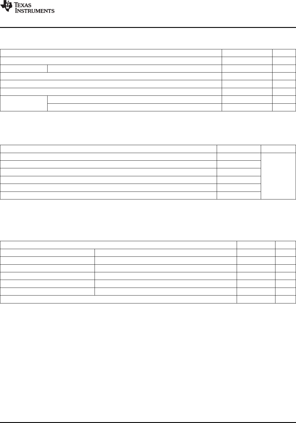
ABSOLUTE MAXIMUM RATINGS
(1)
over operating free-air temperature range, T
A
= 25°C (unless otherwise noted)
VALUE UNIT
V
DD
Supply voltage –0.3 V to 6.0 V
V
I
Input voltage EN, SDA, SCL, IN/TRIG –0.3 to (VDD + 0.3) V
T
A
Operating free-air temperature range –40 to 85 °C
T
J
Operating junction temperature range –40 to 150 °C
T
stg
Storage temperature range –65 to 150 °C
HBM 2000 V
ESD
Protection
CDM 500 V
(1) Stresses beyond those listed under “absolute maximum ratings” may cause permanent damage to the device. These are stress ratings
only, and functional operation of the device at these or any other conditions beyond those indicated under “recommended operating
conditions” is not implied. Exposure to absolute–maximum–rated conditions for extended periods may affect device reliability.
THERMAL INFORMATION
THERMAL METRIC
(1)
VALUE UNITS
θ
JA
Junction-to-ambient thermal resistance 145.2
θ
JCtop
Junction-to-case (top) thermal resistance 0.9
θ
JB
Junction-to-board thermal resistance 105
°C/W
ψ
JT
Junction-to-top characterization parameter 5.1
ψ
JB
Junction-to-board characterization parameter 103.3
θ
JCbot
Junction-to-case (bottom) thermal resistance n/a
(1) For more information about traditional and new thermal metrics, see the IC Package Thermal Metrics application report, SPRA953.
spacer
RECOMMENDED OPERATING CONDITIONS
over operating free-air temperature range (unless otherwise noted)
MIN MAX UNIT
V
DD
Supply voltage VDD 2.5 5.5 V
f
PWM
PWM input frequency IN/TRIG Pin 10 250 kHz
R
L
Load impedance VDD = 5.5 V 8 Ω
V
IL
Digital input low voltage EN, IN/TRIG, SDA, SCL 0.5 V
V
IH
Digital input high voltage EN, IN/TRIG, SDA, SCL 1.3 V
V
I-ANA
Input voltage (analog mode) IN/TRIG 0 1.8 V
f
LRA
LRA Frequency Range 50 300 Hz
Copyright © 2012–2014, Texas Instruments Incorporated Submit Documentation Feedback 3
Product Folder Links: DRV2605