
Datasheet


Table Of Contents
- FEATURES
- APPLICATIONS
- DESCRIPTION
- PINOUT INFORMATION
- ABSOLUTE MAXIMUM RATINGS
- THERMAL INFORMATION
- RECOMMENDED OPERATING CONDITIONS
- ELECTRICAL CHARACTERISTICS
- TIMING REQUIREMENTS
- TYPICAL CHARACTERISTICS
- SYSTEM DIAGRAMS
- APPLICATION INFORMATION
- ECCENTRIC ROTATING MASS MOTORS (ERM)
- LINEAR RESONANCE ACTUATORS (LRA)
- AUTO-RESONANCE ENGINE FOR LRA
- OPEN LOOP OPERATION FOR LRA
- SMART LOOP ARCHITECTURE
- AUTO CALIBRATION
- WAVEFORM LIBRARIES
- WAVEFORM SEQUENCER
- LIBRARY PARAMETERIZATION
- REAL-TIME PLAYBACK (RTP) MODE
- MULTI-MODE INPUT PIN (IN/TRIG)
- DEVICE ENABLE
- CONSTANT VIBRATION STRENGTH
- EDGE RATE CONTROL
- CAPACITOR SELECTION
- MODES OF OPERATION
- BLOCK DIAGRAM
- GENERAL I2C OPERATION
- SINGLE-BYTE AND MULTIPLE-BYTE TRANSFERS
- SINGLE-BYTE WRITE
- MULTIPLE-BYTE WRITE AND INCREMENTAL MULTIPLE-BYTE WRITE
- SINGLE-BYTE READ
- MULTIPLE-BYTE READ
- REGISTER MAP
- DEVICE PROGRAMMING
- WAVEFORM LIBRARY EFFECTS LIST
- PCB LAYOUT RECOMMENDATIONS
- Revision History
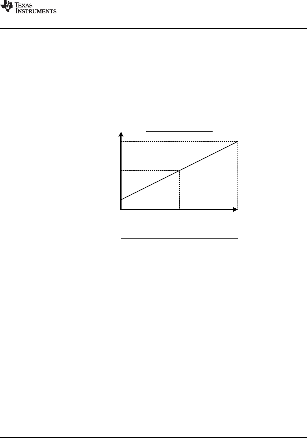
Input
Steady-State
Output Magnitude
RatedVoltage[7:0]
½ RatedVoltage[7:0]
Full Braking
PWM
Input Interface
0% 50% 100%
RTP (8-bit) DataFormat_RTP = 1 0x00
Closed Loop, BiDir_Input = 0
0x7F 0xFF
DRV2605
www.ti.com
SLOS825B –DECEMBER 2012–REVISED JANUARY 2014
Closed Loop Mode, Uni-Directional
In closed loop, uni-directional mode, the DRV2605 gives automatic overdrive and braking for both ERM and LRA
devices. This is the most straight-forward mode to use and understand, and uses the full, 8-bit resolution of the
driver. This mode gives the best performance; however, the data format is not physically compatible with the
open loop mode data that may be used in some existing systems
The reference level for steady-state, full-scale drive is set by the RatedVoltage[7:0] value (once auto calibration
is performed). The output voltage may momentarily exceed the rated voltage for automatic overdrive and
braking, but will not exceed the ODClamp[7:0] voltage. Braking happens automatically based on the input signal
when the back-EMF feedback determines that it is necessary.
Since the system is uni-directional in this mode, only unsigned data should be used. The RTP mode has 8 bits of
resolution over the I2C bus. DataFormat_RTP = 0 (signed) is not recommended for this mode.
Restrictions: For the RTP interface, DataFormat_RTP should be set to 1 (unsigned).
Copyright © 2012–2014, Texas Instruments Incorporated Submit Documentation Feedback 17
Product Folder Links: DRV2605