
Datasheet


Table Of Contents
- FEATURES
- APPLICATIONS
- DESCRIPTION
- PINOUT INFORMATION
- ABSOLUTE MAXIMUM RATINGS
- THERMAL INFORMATION
- RECOMMENDED OPERATING CONDITIONS
- ELECTRICAL CHARACTERISTICS
- TIMING REQUIREMENTS
- TYPICAL CHARACTERISTICS
- SYSTEM DIAGRAMS
- APPLICATION INFORMATION
- ECCENTRIC ROTATING MASS MOTORS (ERM)
- LINEAR RESONANCE ACTUATORS (LRA)
- AUTO-RESONANCE ENGINE FOR LRA
- OPEN LOOP OPERATION FOR LRA
- SMART LOOP ARCHITECTURE
- AUTO CALIBRATION
- WAVEFORM LIBRARIES
- WAVEFORM SEQUENCER
- LIBRARY PARAMETERIZATION
- REAL-TIME PLAYBACK (RTP) MODE
- MULTI-MODE INPUT PIN (IN/TRIG)
- DEVICE ENABLE
- CONSTANT VIBRATION STRENGTH
- EDGE RATE CONTROL
- CAPACITOR SELECTION
- MODES OF OPERATION
- BLOCK DIAGRAM
- GENERAL I2C OPERATION
- SINGLE-BYTE AND MULTIPLE-BYTE TRANSFERS
- SINGLE-BYTE WRITE
- MULTIPLE-BYTE WRITE AND INCREMENTAL MULTIPLE-BYTE WRITE
- SINGLE-BYTE READ
- MULTIPLE-BYTE READ
- REGISTER MAP
- DEVICE PROGRAMMING
- WAVEFORM LIBRARY EFFECTS LIST
- PCB LAYOUT RECOMMENDATIONS
- Revision History
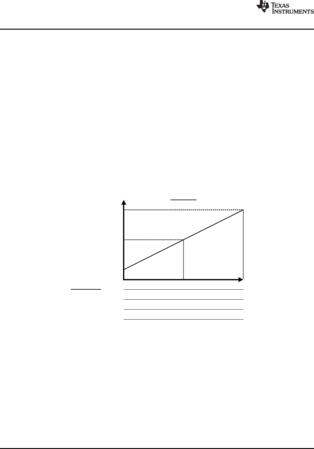
Input
Steady-State
Output Magnitude
ODClamp[7:0]
0 V
Open Loop
ERM_OpenLoop = 1 OR LRA_OpenLoop = 1
RTP (8-bit) DataFormat_RTP = 0
PWM
Input Interface
0% 50% 100%
RTP (8-bit) DataFormat_RTP = 1
0x00 0x7F 0xFF
0x81 0x00 0x7F
-ODClamp[7:0]
DRV2605
SLOS825B –DECEMBER 2012–REVISED JANUARY 2014
www.ti.com
MODES OF OPERATION
The DRV2605 smart loop architecture has three modes of operation. Each of these modes can be used to drive
either ERM or LRA devices.
1. Open Loop Mode
2. Closed Loop Mode (Uni-Directional)
3. Closed Loop Mode (Bi-Directional)
Each mode has its own advantages and disadvantages. The DRV2605 brings a new, cutting-edge actuator
control with closed loop operation around the back-EMF for automatic overdrive and braking; however, some
existing haptic libraries already include overdrive and braking that is embedded in the waveform data. Open loop
mode is used to preserve compatibility with such systems.
The following sections show how the input data for each DRV2605 interface is translated to the output drive
signal.
Open Loop Mode
In open loop mode, the reference level for full-scale drive is set by the ODClamp[7:0] value. A mid-scale input
value gives no drive signal, and less than mid-scale give a negative drive value. For ERM, a negative drive value
results in counter-rotation, or braking. For LRA, this translates to a 180 degree phase shift in commutation.
The RTP mode has 8 bits of resolution over the I2C bus. The RTP data can be in either signed (2’s complement)
or unsigned format as defined by DataFormat_RTP.
Restrictions: Open loop operation for LRA is only valid with the PWM interface. See “Open Loop Operation for
LRA” for details. All input interfaces shown will work with ERM.
16 Submit Documentation Feedback Copyright © 2012–2014, Texas Instruments Incorporated
Product Folder Links: DRV2605