
Datasheet


Table Of Contents
- FEATURES
- APPLICATIONS
- DESCRIPTION
- PINOUT INFORMATION
- ABSOLUTE MAXIMUM RATINGS
- THERMAL INFORMATION
- RECOMMENDED OPERATING CONDITIONS
- ELECTRICAL CHARACTERISTICS
- TIMING REQUIREMENTS
- TYPICAL CHARACTERISTICS
- SYSTEM DIAGRAMS
- APPLICATION INFORMATION
- ECCENTRIC ROTATING MASS MOTORS (ERM)
- LINEAR RESONANCE ACTUATORS (LRA)
- AUTO-RESONANCE ENGINE FOR LRA
- OPEN LOOP OPERATION FOR LRA
- SMART LOOP ARCHITECTURE
- AUTO CALIBRATION
- WAVEFORM LIBRARIES
- WAVEFORM SEQUENCER
- LIBRARY PARAMETERIZATION
- REAL-TIME PLAYBACK (RTP) MODE
- MULTI-MODE INPUT PIN (IN/TRIG)
- DEVICE ENABLE
- CONSTANT VIBRATION STRENGTH
- EDGE RATE CONTROL
- CAPACITOR SELECTION
- MODES OF OPERATION
- BLOCK DIAGRAM
- GENERAL I2C OPERATION
- SINGLE-BYTE AND MULTIPLE-BYTE TRANSFERS
- SINGLE-BYTE WRITE
- MULTIPLE-BYTE WRITE AND INCREMENTAL MULTIPLE-BYTE WRITE
- SINGLE-BYTE READ
- MULTIPLE-BYTE READ
- REGISTER MAP
- DEVICE PROGRAMMING
- WAVEFORM LIBRARY EFFECTS LIST
- PCB LAYOUT RECOMMENDATIONS
- Revision History
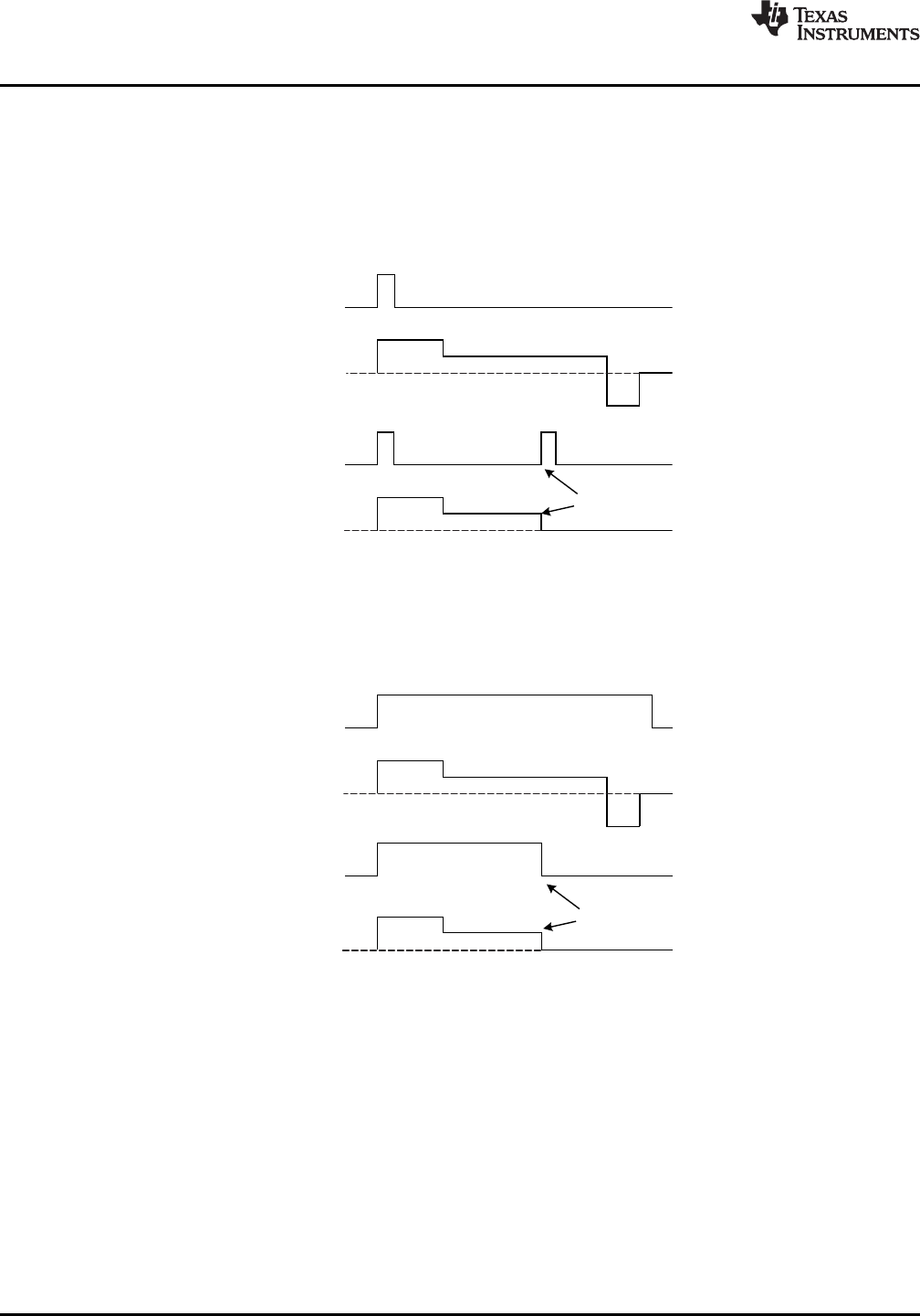
Level Trigger
Haptic Waveform
Level Trigger
Haptic Waveform
Cancellation
Haptic Waveform
Edge Trigger
Haptic Waveform
Edge Trigger
Cancellation
DRV2605
SLOS825B –DECEMBER 2012–REVISED JANUARY 2014
www.ti.com
Input Trigger Options (Continued)
Edge Mode – A low-to-high transition on the IN/TRIG will cause the GO bit to be set. The playback sequence
indicated in the waveform sequencer will play as per normal. The user may cancel the transaction by clearing the
GO bit. Another low-to-high transition while the GO bit is still high will also cancel the transaction, causing the
GO bit to clear and reset. Clearing the trigger pin (high-to-low transition) does nothing, so the user may send a
short pulse without knowing how long the waveform is. The pulse width should be at least 1 µs to assure
detection.
Figure 17. Edge Trigger Mode
Level Mode – The GO bit behavior follows the IN/TRIG pin directly. When the IN/TRIG pin is high, the GO bit is
high, when the trigger pin goes low, the GO bit is cleared; therefore, a falling edge will cancel the transaction.
This can implement a GPIO-controlled buzz on/off controller if an appropriately long waveform is selected. The
user needs to hold the IN/TRIG high for the entire duration of the waveform to complete the effect.
Figure 18. Level Trigger Mode
14 Submit Documentation Feedback Copyright © 2012–2014, Texas Instruments Incorporated
Product Folder Links: DRV2605