
Datasheet


Table Of Contents
- FEATURES
- APPLICATIONS
- DESCRIPTION
- PINOUT INFORMATION
- ABSOLUTE MAXIMUM RATINGS
- THERMAL INFORMATION
- RECOMMENDED OPERATING CONDITIONS
- ELECTRICAL CHARACTERISTICS
- TIMING REQUIREMENTS
- TYPICAL CHARACTERISTICS
- SYSTEM DIAGRAMS
- APPLICATION INFORMATION
- ECCENTRIC ROTATING MASS MOTORS (ERM)
- LINEAR RESONANCE ACTUATORS (LRA)
- AUTO-RESONANCE ENGINE FOR LRA
- OPEN LOOP OPERATION FOR LRA
- SMART LOOP ARCHITECTURE
- AUTO CALIBRATION
- WAVEFORM LIBRARIES
- WAVEFORM SEQUENCER
- LIBRARY PARAMETERIZATION
- REAL-TIME PLAYBACK (RTP) MODE
- MULTI-MODE INPUT PIN (IN/TRIG)
- DEVICE ENABLE
- CONSTANT VIBRATION STRENGTH
- EDGE RATE CONTROL
- CAPACITOR SELECTION
- MODES OF OPERATION
- BLOCK DIAGRAM
- GENERAL I2C OPERATION
- SINGLE-BYTE AND MULTIPLE-BYTE TRANSFERS
- SINGLE-BYTE WRITE
- MULTIPLE-BYTE WRITE AND INCREMENTAL MULTIPLE-BYTE WRITE
- SINGLE-BYTE READ
- MULTIPLE-BYTE READ
- REGISTER MAP
- DEVICE PROGRAMMING
- WAVEFORM LIBRARY EFFECTS LIST
- PCB LAYOUT RECOMMENDATIONS
- Revision History
Input /Output
Accleration
“Ideal” Open-Loop Waveform for
Motor A
Output With Feedback
“Ideal” Open-Loop Waveform for
Motor B
Same Simple Input for
Both Motors
Feedback provides
Optimum Output Drive
DRV2605
www.ti.com
SLOS825B –DECEMBER 2012–REVISED JANUARY 2014
OPEN LOOP OPERATION FOR LRA
The DRV2605 includes an open loop LRA drive mode for legacy systems. This mode is valid for PWM input
mode only. This mode employs a fixed divider that observes the PWM signal and commutates the output drive
signal at the PWM frequency divided by 128. To accomplish LRA drive, the host should drive the PWM
frequency at 128 times the resonance frequency of the LRA. It is important to note that this will not benefit from
the auto resonance tracking feature of the DRV2605.
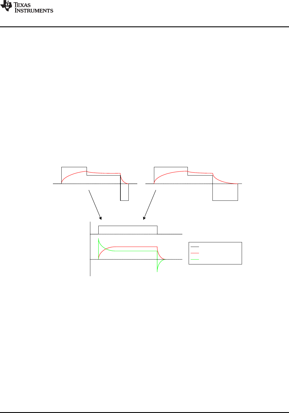
SMART LOOP ARCHITECTURE
A key feature of the DRV2605 is the smart loop architecture, which employs actuator feedback control for both
ERMs and LRAs. The feedback control de-sensitizes the input waveform from the motor response behavior by
providing automatic overdrive and automatic braking.
An open loop haptic system will typically drive an overdrive voltage at startup that is higher than the actuator’s
steady-state rated voltage to decrease the actuator’s startup latency. Likewise, a braking algorithm must be
employed for effective braking. When using an open loop driver, these behaviors must be contained in the input
waveform data. Figure 16 illustrates how two different ERMs with different startup behaviors can both be driven
optimally by the smart loop with a simple square pulse at the input. Note the smart loop works equally well for
LRAs with a combination of feedback control and an auto resonance engine.
Figure 16. Waveform Simplification with Smart Loop
AUTO CALIBRATION
The smart loop architecture utilizes actuator feedback by monitoring the back-EMF behavior of the actuator. The
level of back-EMF can vary across actuator manufacturers due to the specific actuator construction. The auto
calibration compensates for this variation and also performs scaling for the desired actuator according to the
specified rated voltage and overdrive clamp register settings. After the auto calibration is performed, a 100%
signal level at any of the DRV2605 input interfaces will supply the rated voltage to the actuator at steady-state.
The feedback will allow the output level to go above the rated voltage level for automatic overdrive and braking,
but it will not exceed the programmable overdrive clamp voltage.
See “Auto Calibration Procedure” in Device Programming section for details on performing auto calibration.
Copyright © 2012–2014, Texas Instruments Incorporated Submit Documentation Feedback 11
Product Folder Links: DRV2605