
DDR2 Memory Controller User's Guide

www.ti.com
4.8 DDR2 Memory Controller Control Register (DMCCTL)
DDR2 Memory Controller Registers
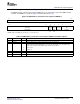
The DDR2 memory controller control register (DMCCTL) resets the interface logic of the DDR2 memory
controller. The DMCCTL is shown in Figure 27 and described in Table 25 .
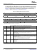
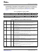
Figure 27. DDR2 Memory Controller Control Register (DMCCTL)
31 16
Reserved
R-0x5000
15 6 5 4 3 2 0
IF
Reserved RESE Rsvd Rsvd RL
T
R/W-0x0190 R/W- R/W- R-0x0 R/W-0x7
0x1 0x0
LEGEND: R/W = Read/Write; R = Read only; - n = value after reset
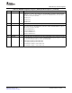
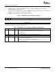
Table 25. DDR2 Memory Controller Control Register (DMCCTL) Field Descriptions
Bit Field Value Description
31-6 Reserved Reserved. Writes to this register must keep this field at its default value.
15-6 Reserved Reserved. Writes to this register must keep this field at its default value.
5 IFRESET DDR2 memory controller interface logic reset. The interface logic controls the signals used to
communicate with DDR2 SDRAM devices. This bit resets the interface logic. The status of this
interface logic is shown on the DDR2 memory controller status register.
0 Release reset.
1 Assert reset.
4 Reserved Reserved. Writes to this register must keep this field at its default value.
3 Reserved Reserved. The reserved bit location is always read as 0. A value written to this field has no effect.
2-0 RL Read latency bits. These bits must be set equal to the CAS latency plus 1.
SPRUEK5A – October 2007 DSP DDR2 Memory Controller 45
Submit Documentation Feedback