
User manual

Functional Description
www.ti.com
2.1 Functional Description
2.1.1 Microcontroller
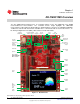
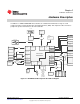
The Tiva TM4C129XNCZAD is an ARM® Cortex™-M4-based microcontroller with 1024-KB flash memory,
256-KB SRAM, 120-MHz operation, USB Host/Device/OTG, Ethernet Controller, Intergrated Ethernet
PHY, Hibernation module, and a wide range of other peripherals. See the TM4C129XNCZAD
microcontroller data sheet for complete device details.
Most of the microcontroller signals are routed to 0.1" pitch break-out pads and labeled with their GPIO
reference. An internal multiplexer allows different peripheral functions to be assigned to each of these
GPIO pads. When adding external circuitry, consideration should be given to the additional load on the
development board’s power rails. The Tiva PinMux Utility can be used to quickly develop pin assignments
and the code required to configure them.
The TM4C129XNCZAD microcontroller is factory-programmed with a quickstart weather display program.
The quickstart program resides in on-chip flash memory and runs each time power is applied, unless the
application has been replaced with a user program.
2.1.2 Clocking
The DK-TM4C129X uses a 25.0-MHz crystal (Y2) to complete the TM4C129XNCZAD microcontroller's
main internal clock circuit. An internal PLL, configured in software, can be used to multiply this clock to
higher frequencies for core and peripheral timing.
The Hibernation module is clocked off of an external 32.768 kHz crystal (Y3).
2.1.3 Reset
The RST signal into the TM4C129XNCZAD microcontroller connects to the RESET switch and to the ICDI
circuit for a debugger-controlled reset.
External reset is asserted (active low) under any one of these conditions:
• Power-on reset
• RESET switch held down
• By the ICDI circuit when instructed by the debugger (this capability is optional, and may not be
supported by all debuggers).
2.1.4 Debugging and Programming
• ICDI: The DK-TM4C129X has a built in debugger, which can be used by connection to a computer
using the included USB micro-B to USB-A plug cable from the microUSB-B connector (J4) located in
the upper right of the board to a USB port on your computer. The on-board ICDI can also be used to
debug external boards using the ARM standard 20-pin connector (J1) and pulling all the shunts from
J3.
• External debugger: an external debugger can be used through the ARM standard 20 pin connector J1.
8
Hardware Description SPMU360–October 2013
Submit Documentation Feedback
Copyright © 2013, Texas Instruments Incorporated