
User manual

BoosterPack XL2
Booster Pack1
Sd Card/ 512 Mbit
EEPROM
SPI/could use quad-spi for higher speed
USB ULPI
Diff pair
OTG- Micro A/B
LED
Tri-color
Magnetic
speaker
driven by
PWM
through
active low
pass filter
ICDI
Logic
Use JTAG or
ICDI
Ethernet w/LEDs
Texas Instruments
TM4C129XNCZADI
USB High speed
MAC
Ethernet MAC
Ethernet Internal
PHY
USB Full speed PHY JTAG-UART0 QSSI3
Expansion Header
MII/RMII
EPI
LCD LIDD 8
CAN0
Up
Select
Down
Switches
Booster Pack2
SPI
I2C
UART
Analog
Timers
CAN
SPI
I2C
UART
EM Connetor
UART
SPI
I2C
QSSI0
I2C3
QSSI2
I2C7
UART5
UART3
I2C6
I2C Temperature
Sensor
20 PIN JTAG
connector
GPIO Timer Pins
3 POS
JUMPER
High speed USB PHY
EPI Partial Host Bus
16/8
Ethernet PHY
QVGA LCD w/
Resistive Touch
Screen
Touch screen
Jumpers
Touch screen ADC
3 POS
JUMPER
Temp.
Sensor
Jumper
USB- Mini B
Chapter 2
SPMU360–October 2013
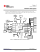
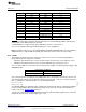
Hardware Description
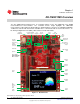
In addition to a TM4C129XNCZAD microcontroller, the evaluation board includes a range of useful
peripheral features and an integrated in-circuit debug interface (ICDI). This chapter describes how these
peripherals operate and interface to the microcontroller.
Figure 2-1. DK-TM4C129X Development Board Block Diagram
7
SPMU360–October 2013 Hardware Description
Submit Documentation Feedback
Copyright © 2013, Texas Instruments Incorporated