
User manual

www.ti.com
List of Figures
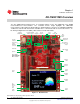
1-1. Board Picture ................................................................................................................ 4
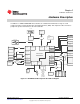
2-1. DK-TM4C129X Development Board Block Diagram ................................................................... 7
2-2. Booster Pack 1............................................................................................................. 11
2-3. Booster Pack 2............................................................................................................. 12
2-4. ULPI, MII, and RMII ....................................................................................................... 13
2-5. Resistive Touch Screen .................................................................................................. 16
2-6. LCD Pin Out................................................................................................................ 16
A-1. DK-TM4C129X Component Locations (Top View).................................................................... 20
A-2. DK-TM4C129X Component Locations (Bottom View)................................................................ 21
A-3. Jumper and Shunt Locations ............................................................................................ 22
List of Tables
1-1. DK-TM4C129X Specifications............................................................................................. 6
2-1. JTAG Pin Table ............................................................................................................. 9
2-2. USB Host/Device/OTG Signals.......................................................................................... 10
2-3. User Buttons and LED Pins.............................................................................................. 10
2-4. J28........................................................................................................................... 13
2-5. J27........................................................................................................................... 14
2-6. J34........................................................................................................................... 17
3
SPMU360–October 2013 List of Figures
Submit Documentation Feedback
Copyright © 2013, Texas Instruments Incorporated