
User manual

Appendix D
SPMU360–October 2013
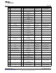
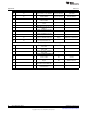
Schematics
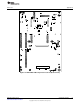
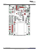
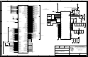
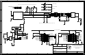
This section contains the schematics for the DK-TM4C129X board.
• Microcontroller, crystals and decoupling capacitors, page 1
• Ethernet, USB, and MII/RMII, ULPI and EPI headers, page 2
• SD card solt, SPI flash, temperature sensor, and speaker with amplifier, page 3
• BoosterPack headers and EM connectors, page 4
• LCD backlight driver, VREF regulator, 3.3V and 5V voltage sources, page 5
• LCD headers, LCD connector, Power LEDs, user LEDs, and user buttons, page 6
• Debug headers, debug jumpers, and ICDI microcontroler, page 7
28
Schematics SPMU360–October 2013
Submit Documentation Feedback
Copyright © 2013, Texas Instruments Incorporated