
User manual

www.ti.com
Functional Description
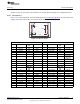
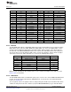
Table 2-6. J34
PIN PORT FUNCTION PIN LCD PIN NAME LCD FUNCTION
1 N/A 5V 2 N/A 5V
3 N/A 3.3V 4 N/A 3.3V
5 PE7 AIN21 6 XR TOUCH ANALOG
7 PT2 GPIO 8 YD TOUCH IO
9 PT3 GPIO 10 XL TOUCH IO
11 PP7 AIN22 12 YU TOUCH ANALOG
13 PF6 LCDMCLK 14 RST SYSTEM RESET
15 PJ6 LCDAC 16 CS CHIP SELECT
17 PR4 LCDDATA00 18 D1 & D10 LCD DATA
19 PR5 LCDDATA01 20 D2 & D11 LCD DATA
21 PF7 LCDDATA02 22 D3 & D12 LCD DATA
23 PR3 LCDDATA03 24 D4 & D13 LCD DATA
25 PR6 LCDDATA04 26 D5 & D14 LCD DATA
27 PR7 LCDDATA05 28 D6 & D15 LCD DATA
29 PS4 LCDDATA06 30 D7 & D16 LCD DATA
31 PS5 LCDDATA07 32 D8 & D17 LCD DATA
33 PR1 LCDFP 34 DC PARALLEL INTERFACE
35 PR0 LCDCP 36 RD READ SIGNAL
37 PR2 LCDLP 38 WR WRITE SIGNAL
39 N/A GND 40 N/A GND
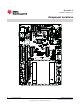
2.1.13 Ethernet
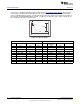
The DK-TM4C129X supports 10/100 Mbps Ethernet through J32. Each DK has been assigned a unique
MAC address that is stored in USER_REG0 and USER_REG1. The value of the MAC address can be
viewed on the Configuration display in the quickstart weather display example. J32 is driven from the
internal PHY of the TM4C129XNCZAD and the PHY controls three LED that indicate Link, Activity and
Speed. The pins used for the Ethernet LEDs can be used for other functions, but the shunts on jumper
J33 must be removed to enable alternative uses. Refer to the following table for pins:
Pin Function LED Color Jumper
PK4 EN0LED0 (Link) RED J33, Pins 1 and 2
PK6 EN0LED1 (Activity) GREEN J33, Pins 3 and 4
PF1 EN0LED2 (Speed) AMBER J33, Pins 5 and 6
RBIAS RBIAS -- NO
EN0RXIN EN0RXIN -- NO
EN0RXIP EN0RXIP -- NO
EN0TXON EN0TXON -- NO
EN0TXOP EN0TXOP -- NO
Note: The pin controlling the Speed LED can be used to control the backlight for the LCD, refer to the
LCD section for information.
2.1.14 Hibernation
The DK-TM4C129X provides a 32.768-kHz crystal (Y3) as a clock source for the TM4C129X Hibernation
module. The board supports hibernation in VDD3ON mode. To measure the current draw during this
mode, see Section 2.1.5.
The sleep mode of the 3.3V regulator can be used by moving the 2.2-kΩ resistor from R2 to R16, which
enables the low power mode of the switcher (U7) when TM4C129XNCZAD (U1) goes into hibernation.
17
SPMU360–October 2013 Hardware Description
Submit Documentation Feedback
Copyright © 2013, Texas Instruments Incorporated