
User manual

0.50
2.20
Ø 0.15x4
3.20
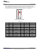
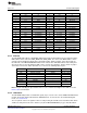
PE7/XR
PT2/XL
PP7/YU
PT3/YD
Functional Description
www.ti.com
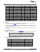
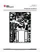
Figure 2-5. Resistive Touch Screen
Note: The analog input PE7 (AIN21) is under commit control and extra steps are required in software to
enable the function of the pin to be changed, see the "Commit Control" section of the datasheet for more
information and the software steps required to enable proper operation of the touch screen.
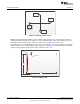
J34 enables the use of another display or other uses of the LCD pins. There are mounting holes under the
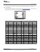
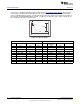
LCD to facilitate the use and mounting of other displays (refer to Figure 2-6 for dimensions). If the default
LCD is used, the default shunts must be in place (shown in Figure A-3).
Figure 2-6. LCD Pin Out
16
Hardware Description SPMU360–October 2013
Submit Documentation Feedback
Copyright © 2013, Texas Instruments Incorporated