
User manual

Functional Description
www.ti.com
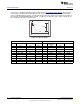
Table 2-5. J27
PIN PORT FUNCTION PIN PORT FUNCTION
1 5V 2 NC
3 PB3 USB0CLK/EPI0S28/EN0MDIO 4 NC
5 GND 6 3.3V
7 PL1 USB0D1/EPI0S17 8 PM3 EPI0S12
9 PL0 USB0D0/EPI0S16 10 PM2 EPI0S13
11 PL2 USB0D2/EPI0S18 12 PM1 EPI0S14
13 PL3 USB0D3/EPI0S19 14 PM0 EPI0S15
15 PL4 USB0D4/EPI0S26 16 PN4 EPI0S34
17 PL5 USB0D5/EPI0S23 18 PA7 EPI0S09
19 PP5 USB0D6 20 PC6 EPI0S05
21 PP4 USB0D7 22 PC5 EPI0S06
23 PP2 USB0NXT/EPI0S29 24 PC4 EPI0S07
25 PB2 USB0STP/EPI0S27 26 HIB
27 PP3 USB0DIR/EPI0S30 28 WAKE
29 PG1 EPI0S10 30 GND
31 PG0 EPI0S11 32 GND
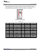
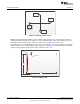
2.1.9 Speaker
The speaker circuit is driven by the PWM coming from PB2(T5CCP0) to produce sound. The amplifier
(U6) is a Texas Instruments LM4819 and is turned on and off by PD4.
The circuit has two filters: a high-pass filter (C14 and R26) and a low-pass filter (C24 and R35). The high-
pass filter removes any DC bias and inaudible frequencies, which the low-pass filter removes the high
frequencies from the PWM pulses.
The amplifier is turned off by default; when PD4 is high the amplifier turns on, and when PD4 is low, the
amplifier turns off.
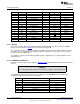
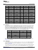
2.1.10 EEPROM and SD Card
Included on the development kit is a Macronix MX66L51235F 512 Mb EEPROM (U2) and a microSD card
slot (J5).
CAUTION
Do not hot plug the SD card, turn off power before adding or removing SD card!
To communicate with these memory devices, use SSI port 3. The EEPROM can use QUAD SSI or
standard SSI, while the SD card uses standard SSI.
Port Function Jumper J7 pins to shunt
PQ1 EEPROM Chip select 1 and 2
PQ0 SSI 3 Clock (used by EEPROM and SD card) 3 and 4
PQ2 SSI 3 Data 0 (EEPROM) or Data out (SD Card) 5 and 6
PF0 SSI 3 Data 1 (EEPROM) or Data in (SD Card) 7 and 8
PF4 SSI 3 Data 2 9 and 10
PF5 SSI 3 Data 4 11 and 12
PH4 SD card Chip Select 13 and 14
14
Hardware Description SPMU360–October 2013
Submit Documentation Feedback
Copyright © 2013, Texas Instruments Incorporated