
User manual

1.80
0.10
0.90
A B
Functional Description
www.ti.com
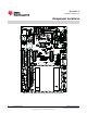
2.1.8.2 BoosterPack 2
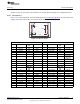
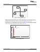
Figure 2-3 is a standard 20-pin BoosterPack (defined in the BoosterPack Design Guide). The port name,
functionality, and voltage rail are printed on the silk screen near the pin. For the BoosterPack 2 UART
port, the following jumpers must be set: J10 and J12 must have the shunts moved to pins 2 and 3 (this is
the side that says BOOSTER2 UART). For SPI, set jumpers J17 and J16 to pin 1 and 2, respectively; for
I2C, set jumpers 16 and 17 to pins 2 and 3.
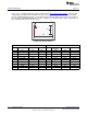
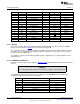
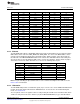
Figure 2-3. Booster Pack 2
J6 J9
Booster
CON A Booster Function TM4C129X DK Function CON B TM4C129X DK Function
Function
1 3.3V N/A GND 1 GND N/A
2 Analog In PD0 AIN15 2 Timer Output PD1 T0CCP0
3 UART RX J12 Jumper 3 INT. GPIO PQ0
4 UART TX J13 Jumper 4 Test N/A NC
5 INT. GPIO PQ1 PQ1 5 RESET RESET RESET
6 SPI A CLK PF3 SSI3CLK 6 SPI_B_SIMO J17/J16 Jumper
7 SPI B CLK PA2 SSI0CLK 7 SPI_B_SOMI J16/J17 Jumper
8 GPIO PS6 8 GPIO PQ2 PQ2
9 GPIO PS7 9 GPIO PN1 PP6
10 GPIO PT0 10 GPIO PN2 PT1
12
Hardware Description SPMU360–October 2013
Submit Documentation Feedback
Copyright © 2013, Texas Instruments Incorporated