
User manual

Functional Description
www.ti.com
2.1.6 USB Host/Device/OTG
The DK-TM4C129X includes a USB Micro-AB (OTG) connector (J24) to allow for USB Host, Device, and
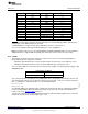
OTG operation. Table 2-2 shows the signals that are used for USB OTG:
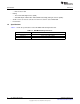
Table 2-2. USB Host/Device/OTG Signals
GPIO Pin Pin Function USB OTG
PL6 USB0DP D+
PL7 USB0DM D-
PB0 USB0ID ID
PB1 USB0VBUS USB VBUS
Load Switch
PG4 USB0EPEN USB VBUS Power Enable (EN)
PG5 USB0PFLT Power Fault (OC)
In USB Host mode, the development board can provide power to the OTG connector. The USB0EPEN
signal controls the enable (EN) of a Texas Instruments’ TPS20511B Load Switch (U5), which enables
power to the connector's VBUS pin.
In Device mode, the development board can be powered from either the ICDI or the 5-V power supply.
In OTG mode, the USB controller is configured as Host or Device depending on the USB0ID signal and
the board is powered appropriately.
2.1.7 User Buttons and User LED
Three push buttons on the board provide navigation and selection for some of the example applications.
These buttons can be used for other purposes in the user’s custom applications.
The development board also has a tri-color user LED.
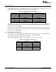
Table 2-3 shows how these features are connected to the pins on the microcontroller.
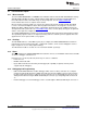
Table 2-3. User Buttons and LED Pins
Pin Pin Function Jumper
PP1 Select SW4 J37 pins 1 and 2
PN3 Up SW2 J37 pins 3 and 4
PE5 Down SW3 J37 pins 5 and 6
PN5 Red LED J36 pins 1 and 2
PQ4 Blue LED J36 pins 3 and 4
PQ7 Green LED J36 pins 5 and 6
10
Hardware Description SPMU360–October 2013
Submit Documentation Feedback
Copyright © 2013, Texas Instruments Incorporated