
- Texas AIP Consumer Audio User's Guide

www.ti.com
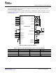
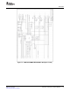
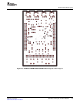
5.5 Connection Diagram for Practical Applications
C
7
Stereo
Headphone
R
2
C
1
C
2
C
3
C
4
C
5
C
6
Low or High
R
1
R
4
SCKI (7)
BCK(1)
LRCK (32)
DIN(2)
DOUT (3)
MO
DE (28)
MS/ADR (29)
MD/SDA (30)
MC/SCL (31)
V
COM
(18)
(11) SPORP
(10) SPORN
(8)HDTI
(16) HPOR/LOR
AIN1L (27)
AIN1R (26)
AIN2L (25)
AIN2R (24)
AIN3L (23)
AIN3R (22)
MICB (21)
(15) SPOLP
(14) SPOLN
(17) HPOL/LOL
(9) HPCOM/MONO
C
10
(20)V
CC
(19) AGND
(12)V
PA
C
11
(13)PGND
(4)V
IO
(5)V
DD
(6) DGND
C
8
C
9
C
13
C
14
C
12
R
3
Monaural
LineOutput
PCM3793A/94A
ToRegulator
Connection Diagram for Practical Applications
The PCM3793A/94A Daughter Card has been configured to measure dynamic audio performance by
common audio analyzer equipment.
In a practical application (such as portable audio player or cellular phone), simple components set up as
shown in Figure 5-15 will be reasonable to save assembly and test spaces. Specific component values
are listed in Table 5-5 .
Figure 5-15. Basic Connection Diagram
Table 5-5. Recommended External Parts for Basic Connection Diagram
Component Recommended Value Component Recommended Value
C1—C6 1 μ F C12, C13 10 μ F–220 μ F
C7 1 μ F–10 μ F C14 1 μ F–10 μ F
C8 0.1 μ F R1, R2 2.2k Ω
C9, C10 1 μ F–4.7 μ F R3 33k Ω
C11 4.7 μ F–10 μ F R4 10k Ω
SBAU127 – July 2007 Evaluation and Measurements 61
Submit Documentation Feedback