
- Texas AIP Consumer Audio User's Guide

www.ti.com
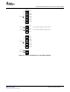
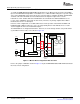
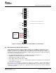
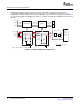
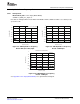
5.4.3.1 LC Low-Pass Filter
Note(1):SameconfigurationatSPORN/SPORP
SPOL
SPOR
J3
J4
SnubberCircuit LCLPF
SPOLN
SPOLP
L122 Hm
L222 Hm
C11
2.2 Fm
C12
2.2 Fm
C9
0.82 Fm
C8
0.82 Fm
R6
330W
R5
330W
R
8
L
W
Audio
Analyzer
Differential
Input
J3
TP2
TP1
+
-
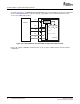
f =
C
» 37.5[kHz]
2 p´ ´
LC
1
(1)
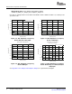
Measurements for Dynamic Characteristics
Daughter Card #2 provides an LC low-pass filter (LPF) to obtain a clean analog signal from the
pulse-width modulated (PWM) output of the speaker output. This configuration is shown in Figure 5-7 .
Additionally, a snubber circuit is inserted into the signal line to achieve the best output power performance
by suppressing ringing in the PWM pulse; however, a snubber circuit will have negligible effects in the end
system.
Figure 5-7. Speaker Output Filter Configuration
Evaluation and Measurements58 SBAU127 – July 2007
Submit Documentation Feedback