
- Texas AIP Consumer Audio User's Guide

www.ti.com
V
COM
AIN3L
AIN2L
AIN1L
AIN2R
AIN3R
AIN1R
MICB
DS
ADC
BCK
DIN
DOUT LRCK
MS/
ADR
MC/
SCL
MD/
SDA
MODE
SerialInterface(SPI/I C)
2
SCKI
AudioInterface
V
PA
PGND V
CC
AGND
V
DD
DGND
HPOL/
LOL
HPOR/
LOR
SPOLP
SPOLN
SPORP
SPORN
HDTI
MUX1
DAL
ADL
DAR
HPCOM/
MONO
COM
HPR
HPL
HPC
LOUT
ROUT
+30dBto
12dB-
+30dBto
12dB-
PG5
V
IO
MONO
MCB
COM
PG1
PG3
PG4
MONO
ADR
D2S
MUX3
MUX2
MUX4
0dBto
21dB-
0dBto
21dB-
PG6
PG2
0dB/
+20dB
0dB/
+20dB
Digital
Filter
Digital
Filter
Digital
Filter
Digital
Filter
MXL
MXR
HPOR
HPOL
COM
V
COM
ATP
(0dBto 62dB,Mute)-
DGC
(0dB/+6dB/+12dB/+18dB)
SilentPopNoise
Controller
ModuleofPossiblePowerUp/Down
PCM3794AhasnoSpeakerOutput
SW1
SW2
SW3
SW6
SW5
SW4
V
COM
PowerOn
Reset
Power
Up/Down
Manager
Clock
Manager
AnalogInputR-Channel
AnalogInputL-Channel
ATR
(Mute)
DS
ADC
DS
DAC
DS
DAC
+
+
+
+6dBto
70dB-
+6dBto
70dB-
+6dBto 70dB-
+6dBto 70dB-
SPL
SPR
MicBias
12
13
14
15
16
17
11
10
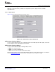
SwitchesSW1toSW6
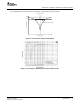
Analog Input Options
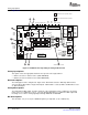
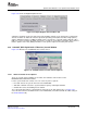
Figure 3-19 illustrates the modules that correspond to the analog path function.
Figure 3-19. Modules Corresponding to Analog Path Function
Analog Input Options
This option selects the appropriate MUX for the respective left or right channel.
• MUX1 selects the L-channel source (AIN1/AIN2/AIN3).
• MUX2 selects the R-channel source (AIN1/AIN2/AIN3).
D2S Select Options
The analog input can be configured as single-end or differential. Select the D2S drop-down menu to
choose between differential or single-ended inputs. If differential is selected, AIN1L and AIN1R are used
as differential inputs.
Analog Mixer Options
The analog input, DAC output, and other channels of the analog input can be combined as an analog
mixer source. To combine the sources, select the Analog Mixer menu to combine the DAC output and
incoming stereo or mono analog signal input through PG1/PG5 or PG2/PG6.
Mic Boost Options
This checkbox sets (or resets) the +20dB microphone pre-amp PG1 (L-ch) or PG2 (R-ch).
Set-Up Guide36 SBAU127 – July 2007
Submit Documentation Feedback