
- Texas AIP Consumer Audio User's Guide

www.ti.com
V
COM
AIN3L
AIN2L
AIN1L
AIN2R
AIN3R
AIN1R
MICB
DS
ADC
BCK
DIN
DOUT LRCK
MS/
ADR
MC/
SCL
MD/
SDA
MODE
SerialInterface(SPI/I C)
2
SCKI
AudioInterface
V
PA
PGND V
CC
AGND
V
DD
DGND
HPOL/
LOL
HPOR/
LOR
SPOLP
SPOLN
SPORP
SPORN
HDTI
MUX1
DAL
ADL
DAR
HPCOM/
MONO
COM
HPR
HPL
HPC
LOUT
ROUT
+30dBto
12dB-
+30dBto
12dB-
PG5
V
IO
MONO
MCB
COM
PG1
PG3
PG4
MONO
ADR
D2S
MUX3
MUX2
MUX4
0dBto
21dB-
0dBto
21dB-
PG6
PG2
0dB/
+20dB
0dB/
+20dB
Digital
Filter
Digital
Filter
Digital
Filter
Digital
Filter
MXL
MXR
HPOR
HPOL
COM
V
COM
ATP
(0dBto 62dB,Mute)-
DGC
(0dB/+6dB/+12dB/+18dB)
SilentPopNoise
Controller
ModuleofPossiblePowerUp/Down
PCM3794AhasnoSpeakerOutput
SW1
SW2
SW3
SW6
SW5
SW4
V
COM
PowerOn
Reset
Power
Up/Down
Manager
Clock
Manager
AnalogInputR-Channel
AnalogInputL-Channel
ATR
(Mute)
DS
ADC
DS
DAC
DS
DAC
+
+
+
+6dBto
70dB-
+6dBto
70dB-
+6dBto 70dB-
+6dBto 70dB-
SPL
SPR
1
2
3
MicBias
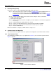
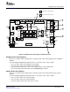
Gain Control for ADC Input Options
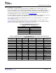
Figure 3-8 shows the EVM modules that correspond to the record function.
Figure 3-8. EVM Modules Corresponding to Record Function
Gain Control for ADC Input Options
Move the L-ch (PG3) and R-ch (PG4) sliders to adjust the gain of the incoming analog signal inputs to the
ADC.
• The L-ch slider manipulates the programmable gain amp (PG3) placed in front of the ADC.
• The R-ch slider controls the programmable gain amp (PG4) placed in front of the ADC.
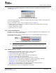
Digital Mute (ATR) Options
Click the respective Digital mute (ATR) checkboxes if a mute function is needed for the ADC digital output.
• The mute checkbox enables a digital soft mute on the ADC for each channel.
• Mute waiting control enables a mute control.
Digital Out Mute Control Options
Select the Digital out mute control drop-down menu to enable the mute time control.
• Apply wait or no wait for the ADC mute.
SBAU127 – July 2007 Set-Up Guide 27
Submit Documentation Feedback