
User manual


8.1 Introduction
8.2 Interrupt Mapping
Introduction
www.ti.com
The TMS320DM646x DMSoC ARM interrupt controller (AINTC) has the following features:
• Supports up to 64 interrupt channels (16 external channels)
• Interrupt mask for each channel
• Each interrupt channel is mappable to a Fast Interrupt Request (FIQ) or to an Interrupt Request (IRQ)
type of interrupt.
• Hardware prioritization of simultaneous interrupts
• Configurable interrupt priority (2 levels of FIQ and 6 levels of IRQ)
• Configurable interrupt entry table (FIQ and IRQ priority table entry) to reduce interrupt processing time
The ARM core supports two interrupt types: FIQ and IRQ. See the ARM926EJ Technical Reference
Manual for detailed information about the ARM’s FIQ and IRQ interrupts. Each interrupt channel is
mappable to an FIQ or to an IRQ type of interrupt, and each channel can be enabled or disabled. The
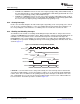
AINTC supports user-configurable interrupt-priority and interrupt entry addresses. Entry addresses
minimize the time spent jumping to interrupt service routines (ISRs). When an interrupt occurs, the
corresponding highest priority ISR’s address is stored in the AINTC’s ENTRY register. The IRQ or FIQ
interrupt routine can read the ENTRY register and jump to the corresponding ISR directly. Thus, the ARM
does not require a software dispatcher to determine the asserted interrupt.
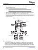
The ARM926EJ CPU core supports 2 direct interrupts: FIQ and IRQ. The ARM interrupt controller (AINTC)
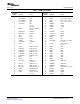
prioritizes up to 64 interrupt requests from various peripherals and subsystems, listed in Table 8-1 , and
interrupts the ARM CPU. Each interrupt is programmable for up to 8 priority levels (6 levels for IRQ and 2
levels for FIQ). Interrupts at the same priority level are serviced in order by the ARM interrupt number,
with the lowest number having the highest priority.
86 ARM Interrupt Controller (AINTC) SPRUEP9A – May 2008
Submit Documentation Feedback