
User manual


7.4.2 DSP Sleep Modes
ARM and DSP Sleep Mode Management
www.ti.com
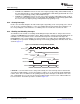
The following sequence describes the procedure to wake up from the wait-for-interrupt mode:
• To wake up from the wait-for-interrupt mode, trigger any enabled interrupt (for example, an external
interrupt).
• The ARM’s PC jumps to the IRQ vector and you must handle the interrupt in an interrupt service
routine (ISR).
Exit the ISR and continue normal program execution starting from the instruction immediately following the
instruction that enabled wait-for-interrupt mode: mcr p15, #0, r3, c7, c0, #4.
Note: The ARM interrupt controller and the module sourcing the wakeup interrupt (for example,
GPIO or watchdog timer) must not be disabled; otherwise, the device will never wake up.
For more information on this sleep mode, refer to the ARM926EJ-S Technical Reference
Manual, which is available from ARM Ltd. at www.arm.com .
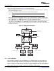
The C64x+ megamodule of the DSP subsystem includes a power-down controller (PDC). The power-down
controller can power-down all of the following components of the C64x+ megamodule and internal
memories of the DSP subsystem:
• C64x+ CPU
• Program Memory Controller (PMC)
• Data Memory Controller (DMC)
• Unified Memory Controller (UMC)
• Extended Memory Controller (EMC)
• L1P Memory
• L1D Memory
• L2 Memory
Although the C64x+ megamodule documentation mentions both dynamic and static power-down, the
DM646x DMSoC supports only static power-down.
• Static power-down: PDC initiates power-down of the entire C64x+ megamodule and all internal
memories immediately upon command from software.
Static power-down affects all components of the C64x+ megamodule and all internal memories. Software
can initiate static power-down via a register bit in the PDC register.
For more information on the DSP subsystem, see the TMS320DM646x DMSoC DSP Subsystem
Reference Guide (SPRUEP8 ).
82 Power Management SPRUEP9A – May 2008
Submit Documentation Feedback