
User manual


6.6.12 Module Control n Register (MDCTL0-MDCTL45)
www.ti.com
PSC Registers
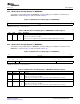
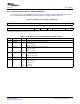
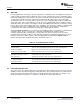
The module control n register (MDCTL n) provides specific control for an individual module. Each module
has one dedicated register. MDCTL n is shown in Figure 6-14 and described in Table 6-18 .
Figure 6-14. Module Control n Register (MDCTL n)
31 16
Reserved
R- 0
15 11 10 9 8 7 3 2 0
Reserved EMUIHBIE EMURSTIE LRST Reserved NEXT
R- 0 R/W- 0 R/W- 0 R/W- 0 R- 0 R/W- 0
LEGEND: R/W = Read/Write; R = Read only; - n = value after reset
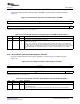
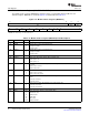
Table 6-18. Module Control n Register (MDCTL n) Field Descriptions
Bit Field Value Description
31-11 Reserved 0 Reserved
10 EMUIHBIE Emulation alters module state interrupt enable.
0 Interrupt is disabled.
1 Interrupt is enabled.
9 EMURSTIE Emulation alters module reset interrupt enable.
0 Interrupt is disabled.
1 Interrupt is enabled.
8 LRST Module local reset control (This bit applies to the DSP module only.)
0 Local reset is asserted.
1 Local reset is deasserted.
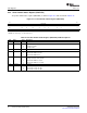
7-3 Reserved 0 Reserved
2-0 NEXT 0-3h Module next state.
0 SwRstDisable state
1h SyncReset state
2h Disable state
3h Enable state
SPRUEP9A – May 2008 Power and Sleep Controller (PSC) 77
Submit Documentation Feedback