
User manual


6.6.11 Module Status n Register (MDSTAT0-MDSTAT45)
PSC Registers
www.ti.com
The module status n register (MDSTAT n) shows the status of each module. Each module has one
dedicated register. MDSTAT n is shown in Figure 6-13 and described in Table 6-17 .
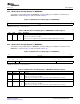
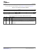
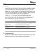
Figure 6-13. Module Status n Register (MDSTAT n)
31 18 17 16
Reserved EMUIHB EMURST
R-0 R-0 R-0
15 13 12 11 10 9 8 7 6 5 0
Reserved MCKOUT MRSTDONE MRST LRSTDONE LRST Reserved STATE
R-0 R-0 R-0 R-0 R-0 R-0 R-0 R-0
LEGEND: R = Read only; - n = value after reset
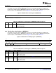
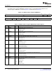
Table 6-17. Module Status n Register (MDSTAT n) Field Descriptions
Bit Field Value Description
31-18 Reserved 0 Reserved
17 EMUIHB Emulation alters module state interrupt status.
0 Interrupt is not active.
1 Interrupt is active.
16 EMURST Emulation alters module reset interrupt status.
0 Interrupt is not active.
1 Interrupt is active.
15-13 Reserved 0 Reserved
12 MCKOUT Module clock output status. Shows status of module clock.
0 Module clock is off.
1 Module clock is on.
11 MRSTDONE Module reset done. Software is responsible for checking that mode reset is done before accessing
the module.
0 Module reset is not done.
1 Module reset is done.
10 MRST Module reset status. Reflects actual state of module reset.
0 Module reset is asserted.
1 Module reset is deasserted.
9 LRSTDONE Local reset done. Software is responsible for checking if local reset is done before accessing this
module.
0 Local reset is not done.
1 Local reset is done.
8 LRST Module local reset status (this bit applies to the DSP module only).
0 Local reset is asserted.
1 Local reset is deasserted.
7-6 Reserved 0 Reserved
5-0 STATE 0-3Fh Module state status: indicates current module status.
0 SwRstDisable state
1h SyncReset state
2h Disable state
3h Enable state
4h-3Fh Indicates transition
Power and Sleep Controller (PSC)76 SPRUEP9A – May 2008
Submit Documentation Feedback