
User manual

5.4.16 PLL Controller Divider n Registers (PLLDIV4-PLLDIV6, PLLDIV8, PLLDIV9)
PLL Controller Register Map
www.ti.com
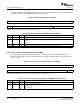
The PLL controller divider n register (PLLDIV n) is shown in Figure 5-19 and described in Table 5-20 .
PLLDIV4 controls the divider for SYSCLK4, PLLDIV5 controls the divider for SYSCLK5, PLLDIV6 controls
the divider for SYSCLK6, PLLDIV8 controls the divider for SYSCLK8, and PLLDIV9 controls the divider for
SYSCLK9. PLLDIV n is not used on PLL2.
Note: On the DM646x DMSoC, all PLL1 SYSCLK n dividers are programmable but you should not
change the divider value to maintain the clock ratios between various modules of the device.
You should only use the power-up default divider values for all PLL1 SYSCLK n dividers for
normal device operation.
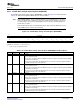
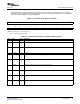
Figure 5-19. PLL Controller Divider n Register (PLLDIV n)
31 16
Reserved
R-0
15 14 4 3 0
D nEN Reserved RATIO
R/W-1 R-0 R/W-5h or 7h
(1)
LEGEND: R/W = Read/Write; R = Read only; - n = value after reset
(1)
For PLLDIV4 and PLLDIV9, RATIO defaults to 5 (PLL divide by 6); for PLLDIV5, PLLDIV6, and PLLDIV8, RATIO defaults to 7 (PLL
divide by 8).
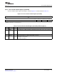
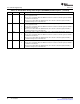
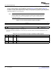
Table 5-20. PLL Controller Divider n Register (PLLDIV n) Field Descriptions
Bit Field Value Description
31-16 Reserved 0 Reserved
15 D nEN Divider enable for SYSCLK n.
0 Disable
1 Enable
14-4 Reserved 0 Reserved
3-0 RATIO 0-Fh Divider ratio. Divider Value = RATIO + 1.
60 PLL Controller SPRUEP9A – May 2008
Submit Documentation Feedback