
User manual
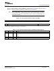

5.4.11 PLL Controller Clock Align Control Register (ALNCTL)
PLL Controller Register Map
www.ti.com
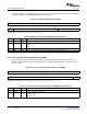
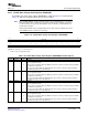
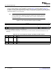
The PLL controller clock align control register (ALNCTL) is shown in Figure 5-14 and described in
Table 5-15 . Indicates which SYSCLKs need to be aligned for proper device operation.
Figure 5-14. PLL Controller Clock Align Control Register (ALNCTL)
31 16
Reserved
R-0
15 9 8 7 6 5 4 3 2 1 0
Reserved ALN9
(1)
ALN8
(1)
Rsvd ALN6
(1)
ALN5
(1)
ALN4
(1)
ALN3
(1)
ALN2
(1)
ALN1
R-0 R/W-1 R/W-1 R-0 R/W-1 R/W-1 R/W-1 R/W-1 R/W-1 R/W-1
LEGEND: R/W = Read/Write; R = Read only; - n = value after reset
(1)
For PLL1 only, not supported for PLL2.
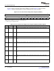
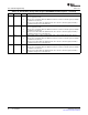
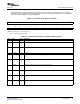
Table 5-15. PLL Controller Clock Align Control Register (ALNCTL) Field Descriptions
Bit Field Value Description
31-9 Reserved 0 Reserved
8 ALN9 SYSCLK9 needs to be aligned to others selected in this register. For PLL1 only, not supported for
PLL2.
0 No
1 Yes
7 ALN8 SYSCLK8 needs to be aligned to others selected in this register. For PLL1 only, not supported for
PLL2.
0 No
1 Yes
6 Reserved 0 Reserved
5 ALN6 SYSCLK6 needs to be aligned to others selected in this register. For PLL1 only, not supported for
PLL2.
0 No
1 Yes
4 ALN5 SYSCLK5 needs to be aligned to others selected in this register. For PLL1 only, not supported for
PLL2.
0 No
1 Yes
3 ALN4 SYSCLK4 needs to be aligned to others selected in this register. For PLL1 only, not supported for
PLL2.
0 No
1 Yes
2 ALN3 SYSCLK3 needs to be aligned to others selected in this register. For PLL1 only, not supported for
PLL2.
0 No
1 Yes
1 ALN2 SYSCLK2 needs to be aligned to others selected in this register. For PLL1 only, not supported for
PLL2.
0 No
1 Yes
0 ALN1 SYSCLK1 needs to be aligned to others selected in this register.
0 No
1 Yes
PLL Controller54 SPRUEP9A – May 2008
Submit Documentation Feedback