
User manual

5.4.3 PLL Control Register (PLLCTL)
www.ti.com
PLL Controller Register Map
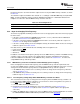
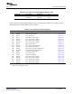
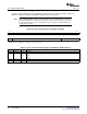
The PLL control register (PLLCTL) is shown in Figure 5-6 and described in Table 5-7 .
Figure 5-6. PLL Control Register (PLLCTL)
31 16
Reserved
R-0
15 9 8 7 6 5 4 3 2 1 0
Reserved CLKMODE Reserved PLLENSRC PLLDIS PLLRST Rsvd PLLPWRDN PLLEN
R-0 R/W-0 R-3h R/W-1 R/W-1 R/W-0 R-0 R/W-1 R/W-0
LEGEND: R/W = Read/Write; R = Read only; - n = value after reset
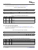
Table 5-7. PLL Control Register (PLLCTL) Field Descriptions
Bit Field Value Description
31-9 Reserved 0 Reserved
8 CLKMODE Reference Clock Selection
0 Internal oscillator
1 CLKIN square wave
7-6 Reserved 1 Reserved
5 PLLENSRC 0 This bit must be cleared before PLLEN will have any effect.
4 PLLDIS Asserts DISABLE to PLL if supported.
0 PLL disable is de-asserted.
1 PLL disable is asserted.
3 PLLRST Asserts RESET to PLL if supported.
0 PLL reset is asserted.
1 PLL reset is not asserted.
2 Reserved 0 Reserved
1 PLLPWRDN PLL power-down.
0 PLL operation
1 PLL power-down
0 PLLEN PLL mode enable.
0 Bypass mode
1 PLL mode, not bypassed
SPRUEP9A – May 2008 PLL Controller 47
Submit Documentation Feedback