
User manual


1.1 Overview
1.2 ARM Subsystem in TMS320DM646x DMSoC
JTAG Interface
System Control
PLLs/Clock
Generator
Input
Clock(s)
Power/Sleep
Controller
Pin
Multiplexing
ARM Subsystem
ARM926EJ-S CPU
16 KB
I-Cache
32 KB RAM
8 KB
D-Cache
8 KB ROM
DSP Subsystem
C64x+t DSP CPU
32 KB
L1 Pgm
128 KB L2 RAM
32 KB
L1 Data
High Definition
Video-Imaging
Coprocessor
(HDVICP0)
Switched Central Resource (SCR)
Peripherals
EDMA I
2
C SPI
UART
Serial Interfaces
DDR2
Mem Ctlr
(16b/32b)
Async EMIF/
NAND/
SmartMedia
ATA
Program/Data Storage
Watchdog
Timer
PWM
System
General-
Purpose
Timer
USB 2.0
PHY
VLYNQ
EMAC
With
MDIO
Connectivity
HPI
McASP
Video
Port I/F
PCI
(33 MHz)
TSIF
High Definition
Video-Imaging
Coprocessor
(HDVICP1)
CRGEN VDCE
Overview
www.ti.com
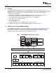
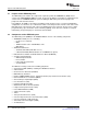
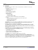
The TMS320DM646x Digital Media System-on-Chip (DMSoC) contains two primary CPU cores: 1) an
ARM RISC CPU for general purpose processing and systems control and 2) a powerful DSP to efficiently
handle image, video, and audio processing tasks. The DMSoC consists of the following primary
components and sub-systems:
• ARM Subsystem (ARMSS), including the ARM926 RISC CPU core and associated memories
• DSP Subsystem (DSPSS), including the C64x+ DSP and associated memories
• Two programmable High-Definition Video Image Coprocessors (HDVICP):
• Video Data Conversion Engine (VDCE)
• Video Port Interface (VPIF)
• A set of I/O peripherals
• A powerful DMA Subsystem and DDR2 memory controller interface
An example block diagram (for the TMS320DM6467 DMSoC) is shown in Figure 1-1 .
The ARM926EJ 32-bit RISC processor in the ARMSS acts as the overall system controller. The ARM
CPU performs general system control tasks, such as system initialization, configuration, power
management, user interface, and user command implementation. Chapter 2 describes the ARMSS
components and system control functions that the ARM core performs.
Figure 1-1. TMS320DM6467 DMSoC Block Diagram
14 Introduction SPRUEP9A – May 2008
Submit Documentation Feedback