
User manual


10.4.4 EMIFA Configuration
10.4.4.1 EMIFA CS2 Bus Width Configuration
10.4.4.2 EMIFA Timing Configuration
10.4.5 PCI Enable (PCIEN) Operation
Default Device Configurations
www.ti.com
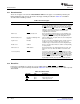
The CS2BW pin determines the default width of the first EMIFA chip select space (EM_CS2). If CS2BW =
0, the space defaults to 8-bits wide; if CS2BW = 1, the space defaults to 16-bits wide. This allows the
ARM to make full use of the width of the attached memory device, if booting from EMIFA or NAND.
Note: CS2BW only selects the default width and needs to be set depending on whether 8-bit or
16-bit EMIFA memory or NAND is used at boot time. After boot, the width of CS2BW can be
changed by software by accessing the appropriate EMIFA control register.
The CS2BW input affects only the first EMIFA chip select space (EM_CS2). All other chip select spaces
default to 8-bits wide and must be modified using the appropriate EMIFA control register if 16-bit operation
is desired.
See the TMS320DM646x DMSoC Asynchronous External Memory Interface (EMIF) User's Guide
(SPRUEQ7 ) for more information on the EMIF.
When EMIFA is enabled, the wait state registers are reset to the slowest possible configuration, which is
88 cycles per access (16 cycles of setup, 64 cycles of strobe, and 8 cycles of hold). Thus, with a 27-MHz
clock at MXI, the EMIFA is configured to run at 4.5 MHz/88, which equals approximately 51 kHz by
default. See the TMS320DM646x DMSoC Asynchronous External Memory Interface (EMIF) User's Guide
(SPRUEQ7 ) for more information on the EMIF.
The PCIEN is latched into the boot configuration register (BOOTCFG) in the System Module from the
PCIEN configuration pin at the end of reset (that is, rising edge of RESET or POR).
The PCIEN configuration signal is used to select the default configuration of the HPI/PCI/EMIFA pins at
reset. This allows the DM646x DMSoC to be PCI-compliant at reset when integrated into a PCI system.
When PCIEN = 1, the PCI module disables the internal pullup and pulldown resistors on the PCI pins and
configures pin multiplexing for PCI. PCIEN is also used in bootmode selection to differentiate between HPI
(PCIEN = 0) and PCI (PCIEN = 1) modes. The PCIEN input must be 0 when the EMIFA boot is selected
but need not be 0 for other boot modes. This allows the device to be part of a PCI system even if booted
from UART, SPI, etc.
See the device-specific data manual for PCIEN pin multiplexing details in the pin multiplexing control 0
register (PINMUX0).
118 Reset SPRUEP9A – May 2008
Submit Documentation Feedback