
User manual


9.3 Device Configuration
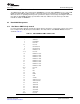
9.3.1 Pin Multiplexing Control
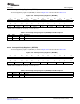
9.3.2 Device Boot Configuration Status
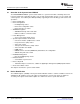
9.3.3 Device Boot Process Status
9.4 ARM-DSP Integration
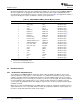
9.4.1 ARM-DSP Interrupt Control and Status
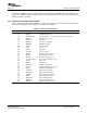
9.4.2 DSP Boot Address Control and Status
www.ti.com
Device Configuration
The system control module contains registers for controlling pin multiplexing and registers that reflect the
boot configuration and boot process status.
The DM646x DMSoC makes extensive use of pin multiplexing to accommodate the large number of
peripheral functions in the smallest possible package. A combination of hardware configuration (at device
reset) and program control controls pin multiplexing to accomplish this. Hardware does not attempt to
ensure that the proper pin multiplexing is selected for the peripherals or that interface mode is being used.
Detailed information about the pin multiplexing and control is covered in the device-specific data manual.
The boot configuration status (BOOTMODE, CS2_BW, PCIEN, and DSP_BT bits) is captured in the boot
configuration register (BOOTCFG) in the System Module. See the device-specific data manual for details
on BOOTCFG.
The boot status register (BOOTSTAT) indicates the status of the device boot process (for example, boot
error, boot complete, or watchdog timer reset). See the device-specific data manual for details on
BOOTSTAT.
The System Module includes registers for generating interrupts from the ARM to the DSP (DSPINT,
DSPINTSET, and DSPINTCLR) and from the DSP to the ARM (DSPINT, DSPINTSET, and DSPINTCLR).
See the device-specific data manual for details on these registers.
The ARM uses DSPINT, DSPINTSET, and DSPINTCLR to generate an interrupt to the DSP. The DSP
interrupt status register (DSPINT) shows the status of the ARM-to-DSP interrupts. The ARM may generate
an interrupt to the DSP by setting one of the four INTDSP n bits or the INTNMI bit in the DSP interrupt set
register (DSPINTSET). The interrupt set (INTDSP n) bit then self-clears and the corresponding bit in
DSPINT is automatically set to indicate that the interrupt was generated. After servicing the interrupt, the
DSP clears the status bit in DSPINT by writing a 1 to the corresponding bit in the DSP interrupt clear
register (DSPINTCLR). The ARM may poll the status bit in DSPINT to determine when the DSP has
completed the interrupt service.
The DSP may generate an interrupt to the ARM in a similar manner using the ARM interrupt set register
(ARMINTSET) and the ARM interrupt clear register (ARMINTCLR). The DSP can monitor the status of the
DSP-to-ARM interrupts using the ARM interrupt status register (ARMINT). See Chapter 12 for more
detailed information.
The DSP boot address register (DSPBOOTADDR) in the System Module contains the DSP reset vector.
See the device-specific data manual for details on DSPBOOTADDR. The boot address defaults to
4220:0000h (EMIF CS2 space) to allow DSP self-boot on power-up (selected by the DSP_BT pin), but
may be changed by the ARM for ARM-controlled booting.
For detailed information on booting the DMSoC, see Chapter 11 .
SPRUEP9A – May 2008 System Control Module 105
Submit Documentation Feedback