
Datasheet


Table Of Contents
- FEATURES
- APPLICATIONS
- DESCRIPTION
- DEVICE INFORMATION
- ABSOLUTE MAXIMUM RATINGS
- THERMAL RESISTANCE FOR TSSOP (PW) PACKAGE
- RECOMMENDED OPERATING CONDITIONS
- RECOMMENDED CRYSTAL/VCXO SPECIFICATIONS
- EEPROM SPECIFICATION
- TIMING REQUIREMENTS
- DEVICE CHARACTERISTICS
- DEVICE CHARACTERISTICS (Continued)
- DEVICE CHARACTERISTICS (Continued)
- PARAMETER MEASUREMENT INFORMATION
- TYPICAL CHARACTERISTICS
- APPLICATION INFORMATION
- Control Terminal Configuration
- DEFAULT DEVICE SETTING
- SDA/SCL SERIAL INTERFACE
- DATA PROTOCOL
- Generic Programming Sequence
- Byte Write Programming Sequence
- Byte Read Programming Sequence
- Block Write Programming Sequence
- Block Read Programming Sequence
- Timing Diagram for the SDA/SCL Serial Control Interface
- SDA/SCL Hardware Interface
- SDA/SCL CONFIGURATION REGISTERS
- PLL MULTIPLIER/DIVIDER DEFINITIONPLL settings limits: 16≤q≤63, 0≤p≤7, 0≤r≤511 to PLL Multiplier/Divider Definition Section
- Revision History
CDCE949
CDCEL949
SCAS844D –AUGUST 2007–REVISED MARCH 2010
www.ti.com
This integrated circuit can be damaged by ESD. Texas Instruments recommends that all integrated circuits be handled with
appropriate precautions. Failure to observe proper handling and installation procedures can cause damage.
ESD damage can range from subtle performance degradation to complete device failure. Precision integrated circuits may be more
susceptible to damage because very small parametric changes could cause the device not to meet its published specifications.
DESCRIPTION
The CDCE949 and CDCEL949 are modular PLL-based low cost, high-performance, programmable clock
synthesizers, multipliers and dividers. They generate up to 9 output clocks from a single input frequency. Each
output can be programmed in-system for any clock frequency up to 230 MHz, using up to four independent
configurable PLLs.
The CDCx949 has separate output supply pins, V
DDOUT
, 1.8 V for the CDCEL949, and 2.5 V to 3.3 V for
CDCE949.
The input accepts an external crystal or LVCMOS clock signal. If an external crystal is used, an on-chip load
capacitor is adequate for most applications. The value of the load capacitor is programmable from 0 to 20 pF.
Additionally, an on-chip VCXO is selectable, allowing synchronization of the output frequency to an external
control signal, that is, a PWM signal.
The deep M/N divider ratio allows the generation of zero-ppm audio/video, networking (WLAN, BlueTooth™,
Ethernet, GPS) or Interface (USB, IEEE1394, Memory Stick) clocks from a reference input frequency, such as
27 MHz.
All PLLs support SSC (Spread-Spectrum Clocking). SSC can be Center-Spread or Down-Spread clocking. This
is a common technique to reduce electro-magnetic interference (EMI).
Based on the PLL frequency and the divider settings, the internal loop-filter components are automatically
adjusted to achieve high stability, and to optimize the jitter-transfer characteristics of each PLL.
The device supports non-volatile EEPROM programming for easy customization of the device to the application.
It is preset to a factory-default configuration (see the Default Device Configuration section). It can be
reprogrammed to a different application configuration before PCB assembly, or reprogrammed by in-system
programming. All device settings are programmable through the SDA/SCL bus, a 2-wire serial interface.
Three programmable control inputs, S0, S1 and S2, can be used to control various aspects of operation including
frequency selection, changing the SSC parameters to lower EMI, PLL bypass, power down, and choosing
between low level or 3-state for the output-disable function.
The CDCx949 operates in a 1.8 V environment. It operates within a temprateure range of –40° C to 85° C.
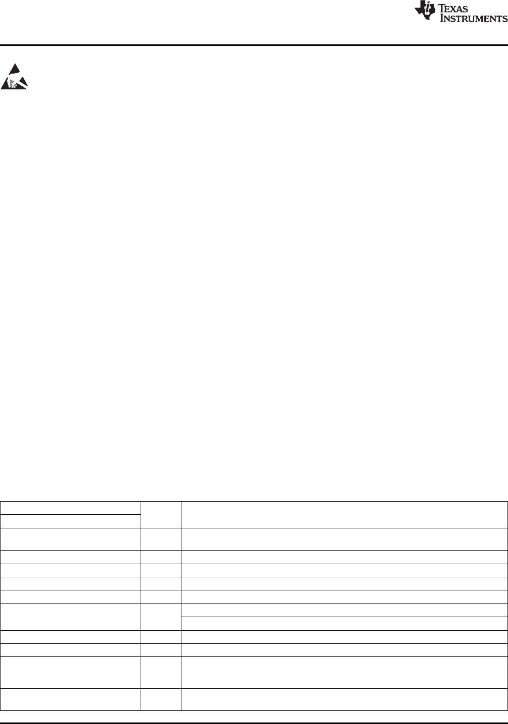
DEVICE INFORMATION
TERMINAL FUNCTIONS
TERMINAL
I/O
NAME NO. (TSSOP24)
21, 19, 18, 7, 8,
Y1, Y2, ...Y9 O LVCMOS outputs
16, 15, 11, 12
Xin/CLK 1 I Crystal oscillator input or LVCMOS clock input (selectable via SDA/SCL bus)
Xout 24 O Crystal oscillator output (leave open or pull up when not used)
V
Ctrl
4 I VCXO control voltage (leave open or pull up when not used)
V
DD
3, 13 Power 1.8V power supply for the device
CDCEL949: 1.8 V supply for all outputs
V
DDOUT
6, 10, 17 Power
CDCE949: 3.3 V or 2.5 V supply for all outputs
GND 5, 9, 14, 20 Ground Ground
S0 2 I User-programmable control input S0; LVCMOS inputs; internal pull-up 500 kΩ
SDA: Bi-directional serial data input/output (default configuration), LVCMOS; internal
SDA / S1 23 I/O / I pull-up 500 kΩ; or
S1: User-programmable control input; LVCMOS inputs; internal pull-up 500 kΩ
SCL: Serial clock input (default configuration), LVCMOS; internal pull-up 500 kΩ; or
SCL / S2 22 I
S2: User-programmable control input; LVCMOS inputs; internal pull-up 500 kΩ
2 Submit Documentation Feedback Copyright © 2007–2010, Texas Instruments Incorporated
Product Folder Link(s): CDCE949 CDCEL949