
User's Manual

CC3200-LAUNCHXL User’s Guide
8
CC3200-LAUNCHXL User’s Guide
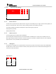
J20
TDI
In
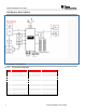
1.1.5 User LEDs and push-buttons
There are 3 user LEDs on the board along with 2 push buttons. The usage can be controlled by the application program.
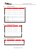
Signal mapping
Reference
Colour
GPIO maping
comment
D7
GREEN
GPIO_11
Glows when GPIO = 1.
D6
YELLOW
GPIO_10
Glows when GPIO = 1.
D3
RED
GPIO_09
Glows when GPIO = 1
SW1
NA
GPIO_13
High when pressed.
SW2
NA
GPIO_22
High when pressed.
1.1.6 On-board sensors
There are two sensors on the board which are connected to the I2C bus. The sensors can be isolated from the I2C bus
using the jumpers J14 and J13. By default the pull-ups on the I2C are not enabled. To enable these install jumpers J7 and
J8.
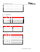
The sensors available on the board are listed below with their address
Reference
Part No
Type
Address
U8
TMP006
Temperature sensor
0x41
U7
BMA222
3-Axis Accelerometer
0X18
Hardware documents
LP V2.0 RevA- PG 1.11
Schematics
Schematics
Assembly diagram
Placement diagram
Bill of materials
Bill of materials
ECO List (Changes made to the sch/bom )
Gerber Files
pcb (Gerber) files
Software Information
1.1.7 USB driver (For BP/LP)
For Windows (XP, Win7) Link