TI Proprietary Information - Strictly Private 2014 CC3200-LAUNCHXL User’s Guide, Ver 1.0 ABSTRACT This document describes the CC3200-LAUNCHXL (CC3200 Launchpad). It details the features of the hardware and also explains the correct usage of the board.
CC3200-LAUNCHXL User’s Guide Contents Introduction............................................................................................................................................. 2 Board overview ................................................................................................................................ 2 Features ..........................................................................................................................................
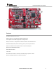
CC3200-LAUNCHXL User’s Guide Features CC3200 WIFI application processor USB interface to PC for CCS/IAR using XDS ICDI USB drivers Flash update over the USB using Simple Link Programmer. 2x20 pin Connectors : Compatible to TI MCU Launch Pads with added functions. Standalone development platform featuring sensors, LEDs and push-buttons Power from USB for the launchpad as well as external boosterpack Operates from 2xAA alkaline battery. Push buttons for RESET 3 user LEDs On-board antenna and U.
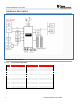
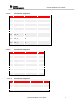
CC3200-LAUNCHXL User’s Guide Hardware description Connector description 1.1.1.1 Pin No P1 connector assignment Signal name Direction w.r.t CC3200 P1.1 VCC(3.3V) OUT P1.2 GPIO03/ADC_CH2 IN P1.3 GPIO_02/UART1_RX IN P1.4 GPIO_01/UART1_TX OUT P1.5 OUT Comments Max 100mA for peripherals UNUSED P1.6 GPIO_04/ADC_CH3 IN P1.7 GPIO_14/SPI_CLK OUT P1.8 GPIO_11 P1.9 GPIO_10/GPIO_12/I2C_SCL BD 2.2K pull-ups on board P1.10 GPIO_11/GPIO_13/I2C_SDA BD 2.
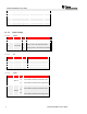
CC3200-LAUNCHXL User’s Guide 1.1.1.2 P2 connector assignment Pin No Signal name Direction w.r.t CC3200 P2.1 GND PWR P2.2 GPIO_22 OUT P2.3 GPIO_17/SPI_CS OUT P2.4 GPIO_28 OUT P2.5 RESET OUT P2.6 GPIO_16/SPI_DOUT OUT P2.7 GPIO_15/SPI_DIN GPIO_10 BD P2.9 GPIO_12 BD P2.10 GPIO_13 BD P3 connector assignment Pin No Signal name Direction w.r.t CC3200 Comments P3.1 5V P3.2 GND P3.3 GPIO_23/TDI IN P3.4 GPIO_24/TDO OUT P3.5 GPIO_28/TCK IN P3.6 GPIO_29/TMS IN P3.
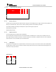
CC3200-LAUNCHXL User’s Guide P4.5 GPIO_06/UART1_CTS IN P4.6 GPIO_28 I/O P4.7 GPIO_07/NWP_LOGGER OUT P4.8 GPIO_05/WLAN_LOGGER OUT P4.9 GPIO_04/WL_RS232_RX IN P4.10 GPIO_03/WL_RS232_TX 1.1.1.5 OUT Jumper settings 1.1.1.5.1 Reference Power Function J22 ICDI Power J23 Board power 1.1.1.5.2 Reference Value Comments Closed Supplies 3.3V to the ICDI 2-3 Supplies 3.
CC3200-LAUNCHXL User’s Guide 1.1.1.5.4 Operating modes (Debug) Mode SOP2 SOP1 SOP0 J11 J9 J10 Functional mode with 4 Wire JTAG 0 0 0 Functional Mode with 2 Wire SWD 0 0 1 Flash programming mode over UART 1 0 0 Note : '0' indicates jumper is open 1.1.2 Power selection The board can be powered from the USB connector using the on-board LDO (3.3V) or using an external battery (2xAA). The battery is connected to J24. There is built-in reverse polarity protection for the battery connector.
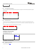
CC3200-LAUNCHXL User’s Guide J20 1.1.5 TDI In User LEDs and push-buttons There are 3 user LEDs on the board along with 2 push buttons. The usage can be controlled by the application program. Signal mapping Reference Colour GPIO maping comment D7 GREEN GPIO_11 Glows when GPIO = 1. D6 YELLOW GPIO_10 Glows when GPIO = 1. D3 RED GPIO_09 Glows when GPIO = 1 SW1 NA GPIO_13 High when pressed. SW2 NA GPIO_22 High when pressed. 1.1.
CC3200-LAUNCHXL User’s Guide CC3200-LAUNCHXL User’s Guide 9
CC3200-LAUNCHXL User’s Guide 10 CC3200-LAUNCHXL User’s Guide
CC3200-LAUNCHXL User’s Guide CC3200-LAUNCHXL User’s Guide 11
CC3200-LAUNCHXL User’s Guide 12 CC3200-LAUNCHXL User’s Guide
CC3200-LAUNCHXL User’s Guide CC3200-LAUNCHXL User’s Guide 13