
User's Guide


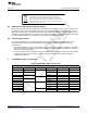
Table Of Contents
- CC3235MODSF SimpleLink™ Wi-Fi® and IoT Solution With MCU LaunchPad™ Hardware
- Table of Contents
- 1 Introduction
- 2 Hardware
- 2.1 Block Diagram
- 2.2 Hardware Features
- 2.2.1 Key Benefits
- 2.2.2 XDS110-Based Onboard Debug Probe
- 2.2.3 Debug Probe Connection: Isolation Jumper Block
- 2.2.4 Application (or "Backchannel") UART
- 2.2.5 JTAG Headers
- 2.2.6 Using the XDS110 Debug Probe with a Different Target
- 2.2.7 Power Connections
- 2.2.8 Reset Pullup Jumper
- 2.2.9 Clocking
- 2.2.10 I2C Connection
- 2.2.11 Sense on Power (SOP)
- 2.2.12 Push-Buttons and LED Indicators
- 2.3 Electrical Characteristics
- 2.4 Antenna Characteristics
- 2.5 BoosterPack™ Header Pin Assignment
- 3 Layout Guidelines
- 4 Operational Setup and Testing
- 5 Development Environment Requirements
- 6 Additional Resources
- 7 Assembly Drawing and Schematics
- Revision History
- Important Notice

TI Confidential – NDA Restrictions
Waste Electrical and Electronic Equipment (WEEE)
This symbol means that according to local laws and regulations your
product and/or battery shall be disposed of separately from household
waste. When this product reaches its end of life, take it to a collection point
designated by local authorities. Proper recycling of your product will protect
human health and the environment.
www.ti.com
EU Certification and Statement
53
SWRU548A–February 2019
Submit Documentation Feedback
Copyright © 2019, Texas Instruments Incorporated
Manual Information to the End User
4.3 Waste Electrical and Electronic Equipment (WEEE)
4.4 OEM and Host Manufacturer Responsibilities
OEM and host manufacturers are ultimately responsible for the compliance of the host and module. The
final product must be reassessed against all of the essential requirements of the RED before it can be
placed on the EU market. This includes reassessing the transmitter module for compliance with the radio
and EMF essential requirements of the RED. This module must not be incorporated into any other device
or system without retesting for compliance as multi-radio and combined equipment.
4.5 Antenna Specifications
In all cases, assessment of the final product must be met against the Essential requirements of RE
Directive Article 3.1(a) and (b), safety and EMC respectively, as well as any relevant Article 3.3
requirements.
1. The antennas listed in Table 12 were verified in the conformity testing, and for compliance the antenna
shall not be modified. A separate approval is required for all other operating configurations, including
different antenna configurations.
2. If any other simultaneous transmission radio is installed in the host platform together with this module,
or above restrictions cannot be kept, a separate RF exposure assessment and CE equipment
certification is required.
5 CC3235MODx Approved Antennas
Table 12. CC3235MODx Approved Antennas
Antenna Information
Brand Antenna Type Model 2.4-GHz Gain 5-GHz Gain
1 Pulse Chip W3078 1.7 4.3
2 Yageo ANT5320LL04R245
5A
2.17 3.51
3 Ethertronics M830520 1 2.6
4 PCB 1000423 -0.6 4.5
5 Laird CAF94504 2 4
6 CAF94505 2 4
7 LSR Dipole 001-0012 2 2
8 080-0013 2 2
9 080-0014 2 2
10 PIFA 001-0016 2.5 3
11 001-0021 2.5 3