
User's Guide
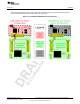
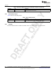
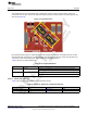

Table Of Contents
- CC3235MODSF SimpleLink™ Wi-Fi® and IoT Solution With MCU LaunchPad™ Hardware
- Table of Contents
- 1 Introduction
- 2 Hardware
- 2.1 Block Diagram
- 2.2 Hardware Features
- 2.2.1 Key Benefits
- 2.2.2 XDS110-Based Onboard Debug Probe
- 2.2.3 Debug Probe Connection: Isolation Jumper Block
- 2.2.4 Application (or "Backchannel") UART
- 2.2.5 JTAG Headers
- 2.2.6 Using the XDS110 Debug Probe with a Different Target
- 2.2.7 Power Connections
- 2.2.8 Reset Pullup Jumper
- 2.2.9 Clocking
- 2.2.10 I2C Connection
- 2.2.11 Sense on Power (SOP)
- 2.2.12 Push-Buttons and LED Indicators
- 2.3 Electrical Characteristics
- 2.4 Antenna Characteristics
- 2.5 BoosterPack™ Header Pin Assignment
- 3 Layout Guidelines
- 4 Operational Setup and Testing
- 5 Development Environment Requirements
- 6 Additional Resources
- 7 Assembly Drawing and Schematics
- Revision History
- Important Notice

TI Confidential – NDA Restrictions
www.ti.com
Hardware
27
SWRU548A–February 2019
Submit Documentation Feedback
Copyright © 2019, Texas Instruments Incorporated
CC3235MODSF LaunchPad™ Development Kit (LAUNCHCC3235MOD)
2.2.12 Push-Buttons and LED Indicators
Table 7 lists the push-button definitions.
Table 7. Push-Button Definitions
Reference Use Comments
SW1 RESET This is used to reset the CC3235MOD device. This signal is also output on the
20-pin connector to reset any external BoosterPack which may be stacked. The
reset can be isolated using the RST jumper at the isolation block.
SW2 GPIO_13 When pushed, GPIO_13 is pulled to VCC.
SW3 GPIO_22 When pushed, GPIO_22 is pulled to VCC.
SW4 Factory default Pressing this button and toggling RESET restores the factory default image on
the serial flash. This can be used to recover a corrupted serial flash, provided
the s-flash was programmed with a recovery image.
Table 8 lists the LED indicators.
(1)
GPIO_10 and GPIO_11 are also used as I
2
C. Whenever the pullups are enabled, the LEDs glow by default without configuring
the GPIOs.
Table 8. LED Indicators
Reference Color Use Comments
D1,D2 Green and Red Debug Indicates the state of the JTAG
emulator. For TI use only.
D3 Yellow nRESET Indicates the state of the NRESET
pin. If this LED is on, the device is
functional.
D4 Red Power Indicates when the 3.3-V power is
supplied to the board.
D7 RGB GPIO_09 Glows when the GPIO is logic-1.
RGB GPIO_10
(1)
Glows when the GPIO is logic-1.
RGB GPIO_11
(1)
Glows when the GPIO is logic-1.
D8 Red Factory Reset Indicates that the push-button for
the factory reset is pressed.
2.3 Electrical Characteristics
For electrical characteristics of the CC3235MODx modules, see CC3235MODx SimpleLink™ Wi-Fi
CERTIFIED
®
Dual-Band Wireless MCU Module data sheet.
2.4 Antenna Characteristics
The CC3235MODSM2MOB and the CC3235MODSF12MOB reference design detail the use of an on-
board antenna. For more information on the antenna VSWR, efficiency, and electrical characteristics, see
M830520.