
User's Guide
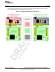
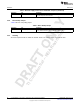
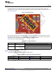

Table Of Contents
- CC3235MODSF SimpleLink™ Wi-Fi® and IoT Solution With MCU LaunchPad™ Hardware
- Table of Contents
- 1 Introduction
- 2 Hardware
- 2.1 Block Diagram
- 2.2 Hardware Features
- 2.2.1 Key Benefits
- 2.2.2 XDS110-Based Onboard Debug Probe
- 2.2.3 Debug Probe Connection: Isolation Jumper Block
- 2.2.4 Application (or "Backchannel") UART
- 2.2.5 JTAG Headers
- 2.2.6 Using the XDS110 Debug Probe with a Different Target
- 2.2.7 Power Connections
- 2.2.8 Reset Pullup Jumper
- 2.2.9 Clocking
- 2.2.10 I2C Connection
- 2.2.11 Sense on Power (SOP)
- 2.2.12 Push-Buttons and LED Indicators
- 2.3 Electrical Characteristics
- 2.4 Antenna Characteristics
- 2.5 BoosterPack™ Header Pin Assignment
- 3 Layout Guidelines
- 4 Operational Setup and Testing
- 5 Development Environment Requirements
- 6 Additional Resources
- 7 Assembly Drawing and Schematics
- Revision History
- Important Notice

TI Confidential – NDA Restrictions
www.ti.com
Hardware
25
SWRU548A–February 2019
Submit Documentation Feedback
Copyright © 2019, Texas Instruments Incorporated
CC3235MODSF LaunchPad™ Development Kit (LAUNCHCC3235MOD)
2.2.10 I
2
C Connection
The board features an accelerometer and a temperature sensor for the out-of-box demo. These are
connected to the I
2
C bus, and can be isolated using the jumpers provided (shown as yellow jumpers J23
and J24 in Figure 13).
Figure 13. I
2
C Connections
By removing J23 and J24, the accelerometer and the temperature sensors are isolated from the I
2
C bus.
This measure also removes the I
2
C pullup resistors from the sensor side of the circuit, and therefore any
connection to the circuit requires the user to install external pullup resistors.
Table 4 lists the I
2
C jumper definitions.
Table 4. I
2
C Jumper Definitions
Reference Use Comments
J23 I2C SCL Populated: CC3235MOD SCL connected to onboard sensors with pullup
Open: CC3235MOD SCL disconnected from onboard sensors
J24 I2C SDA Populated: CC3235MOD SDA connected to onboard sensors with pullup
Open: CC3235MOD SDA disconnected from onboard sensors
2.2.10.1 Default I2C Addresses
Table 5 lists the default I
2
C addresses of the onboard sensors.
Table 5. Default I
2
C Addresses (of Onboard Sensors)
Sensor Type Reference Designator on LP Part Number (Manufacturer) Default Slave Address (Hex)
Temperature (Digital ) U10 TMP116 (TI) 0x49
Accelerometer (Triaxial) U11 BMA280 (Bosch) 0x30